|
|
Tweet |
Color Pictures for the Black-and-White Budget
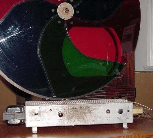 Cliff Benham's Col-R-Tel converter on Philco TV.
|
Color pictures for the common man! Most US families remember Truman, Eisenhower and Kennedy in black and white. Color TV was here, but we couldn't afford it. Then Col-R-Tel, the color TV for champagne tastes on a beer budget, offered color to everyone. At last, the full spectrum was ours! We bolted a wheel onto the front of our TV set. And we switched on a view we'd never seen before! Col-R-Tel, thermionic wonder that it was, turned our cloudy, gray window into a springtime vista. Ah, but we were the few... The brave... The soldering rifle soldiers of the electronic avant garde. For those who missed this beachhead of the red, green and blue, let's return to 1955. Let's smell the rosin, and the dust burning off the 6U8 tubes. Let's have a good look, deep down in the sturdy, Col-R-Tel chassis... |
|
|
|
Col-R-Tel is a 1955, seven-tube color converter for monochrome TV receivers. The manufacturer is Color Converter Inc. of Columbia City, Indiana, near Fort Wayne. Thanks to a splendidly clever design, Col-R-Tel operation is nothing but reliable, simple and effective. Converter electronics recover the color signal and mix it with the monochrome signal. The resulting pictures still appear in black and white. Yet each video field now represents saturation values for one color of the picture. You view the TV through the spinning color wheel. Six wedges of colored plastic make up the wheel. As you watch TV, each wedge colors one video field. The wedges pass by so fast that you can't see them. Your eyes combine the rapidly changing fields into realistic color pictures.
For discussion of any block above, click on that block
Block diagram. Above is a Col-R-Tel block diagram. The obsolete 1951 CBS system, though similar, is incompatible with Col-R-Tel. Col-R-tel owes much to its CBS ancestor: Both systems rely on the field-sequential color technique. Both also use a spinning color wheel. Both scan in the order red, blue and then green. Like the CBS system, Col-R-Tel marks yet another triumph of mechanical television technology. Yet unlike the CBS system, Col-R-Tel is compatible with NTSC, the US television system. Col-R-Tel achieves NTSC compatibility by being two converters in one...
- A mechanical method converts your monochrome TV set to a color set
- An electronic method converts NTSC simultaneous color signals to field-sequential color signals.
On the block diagram, notice that the video signal splits into three paths. The split occurs at the CRT electron gun. Two paths diverge right at the gun. One is the original, monochrome output signal. The second path is the input signal to the Col-R-Tel chroma demodulator. The demodulator processes this signal and outputs a red, green, or blue color signal. At the demodulator input, a third path splits off. This third path is the input signal for the Col-R-Tel burst amplifier. The burst amplifier switches on only during horizontal blanking. For a very brief time, this amplifier accepts the station burst signal. After amplification and processing, this signal becomes the sync reference for the entire color adapter. By phase-shifting this reference, Col-R-Tel can detect separate red, green and blue chroma signals. Circuit operation details appear on succeeding pages.
Viewing experience. In the two demonstrations that I saw, Dave Johnson's Col-R-Tel adapter and DuMont TV maintained perfect sync. The picture was definitely color, and most pleasing. But picture colors were neither bright, nor saturated, nor finely detailed. The color gels really dimmed down the image. Dave compensated by cranking up the TV brightness and contrast. The shadows grew blocky and undetailed. But nobody seemed to mind. Then someone brought down the room lights. I didn't notice a lot of flicker. Yet on Col-R-Tel, motion occasionally caused banding artifacts. Similar artifacts appear in field-sequential color TV pictures from Apollo moon shots.
Overall, the images reminded me of my old RCA CTC-15 set with the color turned partway down. For the demonstration, Dave's program was a videotape. I suppose that the tape could have contributed some of the pastel color effect.
Despite my minor gripes, Dave's Col-R-Tel performed magnificently. The colors were accurate, and they certainly improved image depth. I doubt that anybody would have preferred monochrome. In partial compensation for the minor picture faults, the image had no convergence faults. I don't mean "no observable convergence faults." I mean absolutely no convergence faults, because field-sequential pictures simply avoid them: There's nothing to converge! All the pixels come from one gun.
Col-R-Tel installation requires you to connect several wires between the TV set and three converter boxes. You add the bulleted parts in the block diagram.
- The first converter box contains color-decoding electronics. These electronics include two sections: The demodulator section and the burst section.
- The second box contains the disc module. Inside the module are the color disc, drive motor, and a two-level, commutating switch. One switch level selects the red, blue, or green color subcarrier phase for the demodulator. The other level applies the wedge-change signal to the motor control amplifier.
- The third box contains size control resistor, coils and capacitor. These parts load the yoke coils and reduce picture size to about 14 inches across. Why reduce picture size? Because that way, the scanning disc can be a manageable size.
The System for builders. If you're a color wheel builder, investigate the Col-R-Tel system! Unlike the CBS system, Col-R-Tel is compatible with our NTSC TV system. While revolutionary in 1955, Col-R-Tel electronics are reasonably simple. Col-R-Tel contains very few tuned coils and transformers. Diodes, rather than triodes or pentodes, switch between color signals. Today, a builder might easily replace these diodes with solid-state devices. Col-R-Tel engineers eliminated color bandpass amplifiers. Field-sequential scanning reduces the number of output demodulator and driver stages from six to two. Many of the tubes are triodes, and most are dual or triple types. Unlike most color decoders, Col-R-Tel requires no delay line for the luminance signal.
|
What it can't do. Neither Col-R-Tel nor the CBS system can convert black and white broadcasts. These devices don't colorize monochrome pictures. Instead, both require color broadcasts on a monochrome picture tube. Because Col-R-Tel is an adapter, it also poses requirements for the TV receiver. The receiver must have a broadband, intermediate frequency (IF) amplifier. Otherwise, the IF amplifier will filter out too much of the color signal. Here's why: The unused chroma subcarriers appear at the monochrome CRT. Most adapters, including Col-R-Tel, extract the signals there. No bandpass or equalization stage amplifies these signals. Suppose that the TV's IF amplifier shears off most of the color subcarriers and burst signal. Then Col-R-Tel has nothing to work with. Ingenuity to the rescue. What Col-R-Tel can't do provides opportunity for the ingenius experimenter. The circuit is simple and effective. Col-R-Tel simply invites further innovation. Who knows? Maybe someone will add an automatic color control (ACC) or automatic tint control (ATC). Case in point: Cliff Benham's Col-R-Tel converter refused to work with his Pilot TV set. The set clipped off the chroma signal, and that was that. Ah, but never say "die." Cliff ordered a Sams schematic set and rolled up his sleeves. Peering at the schematic, Cliff wondered if the sound trap were the problem. One way to find out! In an eyeblink, Cliff soldered a jumper across the trap. Then he flipped on the set and Col-R-Tel unit. Wow! Color TV! Another satisfied 1960 family! |
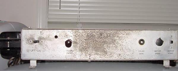
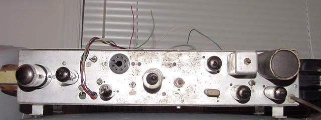
Today, Cliff is repairing his 1960 Col-R-Tel converter. Soon, the 7-tube wonder will be ready to go! (Top: Front view; Bottom: back view.) |
Go to Page: 1 2 3 4 5 6 7 8 9 Next
COL-R-TEL CONTENTS
- OVERVIEW
- Block diagram summary
- Viewing experience
- Installation
- System for builders
- What it can't do
- Ingenuity to the rescue
- DEMODULATOR SECTION
- BURST SECTION
- MOTOR CONTROL SECTION
- SIZE CONTROL SECTION
- PERFORMANCE COMPARISON
- DRAWBACKS
- OTHER COLOR ADAPTERS
- COL-R-TEL ENHANCEMENTS
- BEST TV SET FOR COL-R-TEL
- COLOR WHEEL TV FAQ
- HOW TO WIND DELAY LINES
- CLIFF BENHAM REDESIGNS COL-R-TEL
- TRANSISTORIZING COL-R-TEL
- COL-R-TEL 101: THE BASICS
- COL-R-TEL ON THE MOON
- COL-R-TEL INSTALLATION INSTRUCTIONS
- COL-R-TEL OPERATING INSTRUCTIONS
- COL-R-TEL, MISSING MANUAL PAGES
- TWO-COLOR TV
- Back to top