|
|
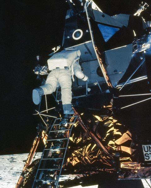
Illusion GeneratorThe moon landings transported humanity to a new frontier. This grand adventure also offered a personal scale. Each viewer shared the astronauts' observations. Each of us beheld the lunar landscape for himself. For the worldwide audience, the Apollo astronauts became our Apollo astronauts. As they spoke with us, we all joined Mission Control. We saw what they saw. We delighted in their personal words and thoughts. Newsmen and engineers explained to us technical details that college physics students had never heard. For a brief moment, each of us had a seat on the world's most powerful spacecraft. Only through television could this event be possible. Here was a true example of television, not as a box of electronics, but as illusion generator. The Apollo astronauts took a rocket to the moon and back. Via television, the rest of us soared through 500,000 miles of virtual space. Illusion generator though it was, television was our true distant vision. Television portrayed the moon as it grew close. At the television, we drew a sigh of relief as our LEM touched down. And by television, we matched our footfalls to the first steps on the lunar surface. Our friend with the camera was there. And this camera brought us all along. In television history, we have found no more compelling use for the medium. Moon tech. Apollo moon television differed from the TV that we watched in our homes on Earth. NASA briefed the media on the differences. |
||
|
Spinning wheel. We heard about the spinning wheel in front of color moon TV cameras. Electronics brought us the black-and-white part of the picture. But the color wheel brought us the hues. Mechanical TV had returned to open another technical outback! Not the CBS color TV system. Newspaper stories mentioned that this mechanical color system was really the CBS color system: The very same system that the US had abandoned in 1951. Quaint, but inaccurate. The CBS color TV system didn't really go to the moon. A CBS color set couldn't lock the moon color picture. In fact, a CBS set couldn't even lock a monochrome picture from the moon. With a CBS color TV, at best, all you'd have seen would be flipping streaks. FACT: Apollo moon TV was really Col-R-Tel. |
|||
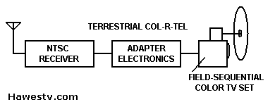
Terrestrial Col-R-Tel
What was Col-R-Tel? Let's define some terms and recount some related TV technical history...
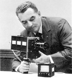
1955 Col-R-Tel converter from back of TV. (Luckett, 1955, p. 137) |
|
Connections. There are several connections between Col-R-Tel and the color mooncams that debuted some 14 years later...
| |
How Terrestrial Col-R-Tel WorkedOnly the wheel. Col-R-Tel adopted the CBS color wheel, the CBS system's most distinctive feature. The CBS system used one wheel before the studio camera. A matching and synchronized wheel rotated in front of the home receiver, painting colors over the TV picture. Differences. Unlike the CBS system, Col-R-Tel only needed a color wheel at the receiver. Col-R-Tel electronics differed markedly from CBS system circuits. On screen, the difference was obvious: Col-R-Tel could reproduce standard, off-air, NTSC color TV signals. The CBS system couldn't. CBS electronics were proprietary. Col-R-Tel electronics were a unique design, too, but that design borrowed heavily from NTSC color tech. The mechanical part of a Col-R-Tel kit was a plastic color wheel. Six transparent, colored wedges made up the wheel. A user mounted the wheel in front of the picture tube. Viewers watched the picture through the spinning wheel. As the wheel spinned, it added hues to the picture. | |
|
Col-R-Tel kit electronics added color saturation values to the picture. Normally, CRT brightness (luminance) was the sum of three color values. The kit's color saturation values added or subtracted from this sum. Of course, the display was still monochrome. Yet when watching through the color disc, the viewer perceived true color pictures. An adapter circuit modified incoming NTSC-standard color signals to produce field-sequential color signals. The electronics also kept the wheel in step with station color signals. |
From Col-R-Tel to MooncamsMooncams had to travel through space, pulling multiple G-forces during takeoffs and landings. These cameras had to operate over a 500-degree temperature range. Despite all this abuse, mooncams had to be reliable. And there was more: Mooncams had to use as little power and bandwidth as possible. Mooncams had to be lightweight and portable. They couldn't be temperamental. Complicated tube alignment and optical balancing procedures were out of the question. With all these requirements, no studio color camera of the 1960s could measure up. The Answer: Field-Sequential Color. Westinghouse designers found a solution in field-sequential technology, the stuff of Col-R-Tel and the CBS color system. This technology only required one tube, so out went the tube-alignment procedures. Meanwhile, the weight and power requirements dropped to one-third or one-fourth. Bandwidth reduction was possible, since only one color transmitted at a time. (Mooncams didn't transmit chroma, burst, or wideband luminance signals.) Specialized camera tubes (Westinghouse's “SEC” and RCA's “SIT”) could operate in extreme lighting conditions. Reflective coatings protected the cameras from the temperature extremes of lunar days and nights. New integrated circuits and transistors shrunk the electronics. And like Col-R-Tel, every color mooncam sported a color wheel. |
|
Lunar Col-R-Tel
|
Westinghouse Moon cameras. For the early Apollo missions, Westinghouse designed and supplied monochrome and color cameras. At Westinghouse, Stanley Lebar was the Apollo TV camera program manager. Stan led the camera development group. Larkin Niemyer directed engineering efforts on the color cameras. Beginning with Apollo 10, lunar missions included a color mooncam in the Command Module. |
|
|
On Apollo 10, astronaut Thomas Stafford enthusiastically promoted the cabin color camera. The results from the Westinghouse field-sequential color system were nothing but spectacular. After the mission, NASA decided to include color cameras on future missions. These missions transmitted color TV pictures from Westinghouse (WEC) cameras in their command modules. Apollo 12 was the first mission to deploy a color camera on the lunar surface. Yet due to an operator error early in the mission, Apollo 12's surface camera failed. Apollo 13 developed serious equipment problems, and couldn't land. Apollo 14 achieved the first successful color TV transmissions from the lunar surface.
|
|
|
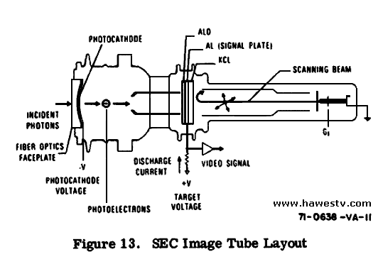
SEC Tube. Westinghouse (WEC) used a type WL30691 SEC (Secondary Electron Conduction) pickup tube in its TV mooncams. According to Westinghouse, SEC advantages include “...its size, weight, power requirements, ruggedness, stability, and simplicity of operation.” Low-light capability and lack of lag are particularly important characteristics of the SEC. “Lag is a problem when viewing a moving scene, generally resulting in a loss of resolution...” (Niemyer 5) |
||
|
Inside the SEC tube, the target had an image size of 0.5 by 0.375 inch. Basically, the SEC tube was a vidicon with an image intensifier (electron multiplier) in front of the target. Light produced plentiful secondary electrons, amplifying the image on the faceplate. Between scans, the target stored and integrated the secondary electrons. Beyond the target, scanning by electron beam proceeded as in a vidicon: Scanning caused a changing video potential to develop across the output resistor. (Lebar & Hoffman 2-5)
|
|
|
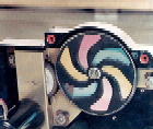
Moon color wheel. Moon cameras included a small color wheel in front of the camera lens. This wheel measured some three inches across. It rotated at 599.94 rpm. The color wheel photo, top-right, above, shows the back of the Westinghouse color wheel assembly from an Apollo mooncam. This part of the color wheel faced the camera body. To the left of the wheel you can see the three-to-one driver wheel. The driver rotated in the reverse direction (clockwise here, from behind the lens) at 1799.82 rpm. The motor shaft, rotating counterclockwise, appears to the left of the driver. Comparing color wheels. The moon color wheel was practically the same as the terrestrial Col-R-Tel wheel. The main difference was that moon wheels had broader borders between color wedges. Otherwise, both terrestrial and lunar Col-R-Tel wheels resembled the original, CBS wheel. The late Stanley Lebar told me that the mooncams scanned the tube in R-B-G order. This is the order that CBS inventor Peter Goldmark specified. Col-R-Tel also followed this CBS color order spec. (CBS research with test audiences proved that R-B-G was the preferred order.) Yet in both terrestrial and lunar Col-R-Tel, the electronics differed from the CBS electronics. Apparent vs. actual colors. The WEC color wheel photo originally appeared in “The Color War Goes to the Moon” by Stanley Lebar. Note: The colors on this wheel appear to be cyan, yellow and magenta. As Stan explained to me, these are the complements of the filtered colors red, blue and green. The glass dichroic filters reflect complements and pass filtered colors. Notice the six filter wedges on the color wheel: The convex sides of each filter wedge are the leading edges. This disc would turn counterclockwise. A retouched negative picture shows the actual filter colors. To see these colors, click the photo. |
|
|
Goldmark's CBS patent (U.S. patent 2,304,081) includes his color wheel drawing, bottom-right, above. Note the similarity to the mooncam color wheel. Goldmark's color wheel turns counterclockwise, the same way as the Lebar wheel does. (See the direction arrow in the center.) To view a color version of Goldmark's wheel, click the drawing. Moon color wheel differences. I mentioned the moon color wheel's broad borders between color wedges. These opaque borders allowed time to finish scanning one color video field. Afterward, the next color filter swung into place. Colors scanned across the camera at the standard NTSC vertical frequency, 59.94 Hz. |
|
|
RCA cameras. RCA supplied color cameras for Apollo 15, 16 and 17. The RCA camera had an image area of 0.5 by 0.38 inch, about the same as in the WEC camera. (RCA, Ultricon and SIT 10) One of RCA's important contributions was that it corrected the picture gamma (brightness in relation to signal strength). |
|
|
The SIT tube design. RCA used a different type of image intensifier than the one in the WEC camera. In RCA's version, an matrix of silicon photodiodes multiplied the incident light. Gain could exceed 3,000. The diodes output photoelectrons to the target. The target performed its traditional charge-storage function. After the target, the tube followed vidicon theory: An electron beam scanned and cleared the target charges. The output resistor developed a varying voltage in proportion to the input video. (RCA manual 1-22)
|
|
|
Less blooming. The gamma correction circuit reduced the blooming or clipping of bright picture details. Gone were the Smurf-like astronaut pictures that viewers noticed in previous Apollo television transmissions! Since Mission Control in Houston could remotely operate the RCA camera, the camera could follow the lunar liftoff. RCA dubbed the camera the Ground-Controlled Television Assembly or GCTA. Soon after the camera's introduction, astronauts shortened the name to “gotcha.” Robert G. Horner managed the engineering design team. Sam Russell was RCA's project engineer for the Apollo cameras. A link to his story appears at the end of this article.
|
|
Removing Subcarrier Interference
|
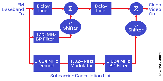
Troublesome Subcarriers. During Apollo 12 and 14, a low-pass filter removed two interfering subcarriers from the FM video passband. The subcarriers occurred at 1.024 MHz (voice/biomed) and 1.25 MHz (telemetry). Unfortunately, the filter limited the upper video bandwidth to 750 kHz. This abnormally low top frequency resulted in a drastic loss of picture detail. At Goldstone, Dick Nafzger and his team designed a far better subcarrier elimination method. The new circuit allowed mooncams to send higher-definition pictures to the Earth.
|
|
|
|
The new subcarrier cancellation unit dealt separately with artifacts of the two subcarriers.
NASA used the subcarrier cancellation unit for missions 15 through 17. Noise ReductionImage Transform received a NASA contract to reduce noise in lunar video. This extra processing smoothed and sharpened mooncam pictures during Apollo 16 and 17. Image Transform was a North Hollywood, California concern. In nearly real time, it polished video feeds from lunar surface EVAs (extravehicular activities). After this processing, the video returned to Houston for dissemination to worldwide TV networks. |
||
Go to Page: 1 2 3 Next
Index
- Illusion Generator
- Terrestrial Col-R-Tel
- How Terrestrial Col-R-Tel Works
- From Col-R-Tel to Mooncams
- Lunar Col-R-Tel
- Noise Reduction