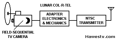
How the Downlink Converts Moon Signals
|
Moon Col-R-Tel used its fields in a different way than Earth TV did. Moon video painted a color picture in six fields. But Earth TV painted that color picture in only two fields. For this reason, video coming from the Moon required conversion before we could view it. Video 101. We need to define a few terms: A frame is one picture in a series that appears as moving video. Earth televison systems built each video frame from two fields. A field was half of a video frame. Each field contained alternate scan lines: Odd lines in one field. Even lines in the other. The scan lines ran left to right, and drew the picture on the screen. Back to the two video fields. Over time, two fields meshed, reducing flicker effects for the viewer. |
|
Moon vs. Earth Col-R-Tel. The Moon color system was Earth Col-R-Tel in reverse. Recall that Earth Col-R-Tel transformed NTSC television signals into field-sequential signals. Video from the Moon was another matter. It was already field-sequential. The Earth downlink station translated this video to NTSC. Standard TV sets could reproduce the downlink station's output. Downlink adapters made viewable pictures for home sets across the world. Now let's take a deeper look at the video arriving from the Moon. |
 |
Mooncam ProcessThe mooncam process complemented downlink station processes: The mooncam selected one of three colors per field and transmitted that color to the downlink station. Filters in the color wheel caused the camera to ignore or skip the other two colors. Skipping colors reduced the video bandwidth. Due to color-skipping, each color in a mooncam video only updated once per every three video fields. (Wetmore 20) Note: The output of an Earth Col-R-Tel adapter followed the same, lossy mooncam process. |
WEC Mooncam for lunar surface, color (Wood 29) |
Color sensor. RCA's GCTA camera transmitted a “field complete” signal. The camera relayed this signal during the horizontal interval of line 18. Before every green field, a phototransistor picked up a lamp shining through an aperture in the color wheel. There were two such apertures in the wheel. For this reason, every time the wheel revolved, the phototransistor pulsed its signal twice. (RCA 1-12, 1-20, 1-28, 1-29, 1-30, 1-35, & 1-36) The downlink station could use the “field complete” signal as a reference. This reference allowed the downlink to route the correct signal to each input of the color matrix and proc amp.
The WEC camera used a magnet and coil to detect a similar signal. (Apollo Color Television Subsystem Operation and Training Manual 3-9)
(R= Red; B= Blue; G= Green)
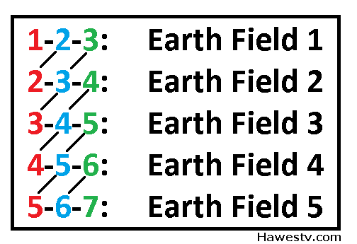
| Moon Frame 1 | Moon Frame 2 | Moon Frame 3 | |||
|
Field 1: R (Odd) |
Field 2: B (Even) |
Field 3: G (Odd) |
Field 4: R (Even) |
Field 5: B (Odd) |
Field 6: G (Even) |
| Skip B (Odd) | Skip G (Even) | Skip R (Odd) | Skip B (Even) | Skip G (Odd) | Skip R (Even) |
| Skip G (Odd) | Skip R (Even) | Skip B (Odd) | Skip G (Even) | Skip R (Odd) | Skip B (Even) |
|
Transmit R (Odd) |
Transmit B (Even) |
Transmit G (Odd) |
Transmit R (Even) |
Transmit B (Odd) |
Transmit G (Even) |
|
Two Machines. Houston corrected the signals for Doppler shift. NASA used two, quadruplex, 2-inch videotape machines. One machine recorded. We'll call this machine the recorder. The other machine played back. We'll call this machine the player. (Wood, 7) The two machines operated as an electromechanical time base corrector. Tape from the recorder ran to the player. Between the recorder and player, the tape was nearly slack. This slackness allowed one machine to operate faster than the other without breaking the tape. There was another complication: Normally when tape tension slackens, a tape sensor shuts down a tape machine. The answer to this problem was a counterweight between the players. The counterweight maintained just enough tape tension. This constant tension kept the tape sensors from stopping either machine. (Wetmore, 20) |
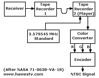
Doppler corrector, field storage unit and NTSC encoder. (The “Color Converter” was a video disc recorder.) Source: Apollo Color Television Subsystem Operation and Training Manual 5-2. |
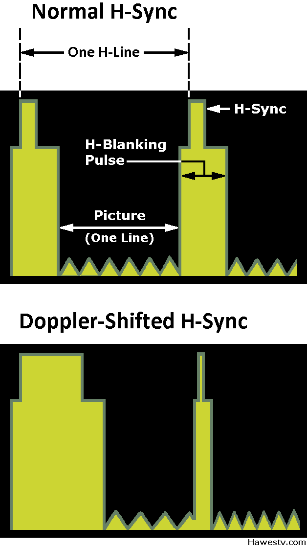
The recorder taped the TV signal from the spacecraft. This TV signal included sync pulses that stabilized the picture. On the tape, the time between recorded sync pulses varied. This time depended on the direction of spacecraft motion with respect to Earth: When the spacecraft receded, intervals between sync pulses grew longer. When the spacecraft approached, the intervals grew shorter. On the Moon, heating and cooling of the sync generator circuits caused more phase shifts. (Wood 12)
Servo. A crystal-controlled servo drove the player. This servo locked on the NTSC color subcarrier frequency, 3.58 MHz. The servo’s other input was the taped horizontal sync pulses from the recorder. Normally, these horizontal sync pulses followed the NTSC standard and occurred at 15,734 Hz. The crystal frequency and the normal sync frequency had a common quotient of 7,867 Hz: The servo divided the crystal frequency by 455 to produce a 7,867-Hz signal. The servo also divided the horizontal frequency by two. Normally this operation would also produce 7,867 Hz. Yet due to Doppler shift, the result might be off by several Hz.
Subcarrier quotient. As its standard, the servo used the crystal subcarrier quotient (7,867 Hz). The servo compared the two quotient frequencies. Any difference between these two frequencies caused a correction voltage. The servo used this correction voltage to vary the player speed. The varying player speed corrected for differing intervals between sync pulses. Output sync matched the NTSC standard. The player's video output ran to the scan converter.
|
The downlink picture conversion process was analog. The idea was to record Moon fields serially and play them back in parallel. To store, repeat and combine Moon video fields, the Apollo missions used magnetic disc recorders. Ampex developed this type of recorder for use in sporting events. Starting in 1967, such recorders made possible the instant replays that football fans love. (Abramson, 117-118) Westinghouse modified Ampex HS-100 recorders for use in NASA downlink stations. The stock HS-100 recorder had two discs, and recorded on both sides of each one. This recorder contained 1,800 tracks (450 tracks per side, times two discs). Each track could record one video field. Alternate fields recorded on alternate disc sides. The HS-100 disc rotated at 3,600 rpm. In one rotation, each side of each disc could record or play back one video field. The next video field would record on the next side. There were four record-play-erase heads, one for each side of the two discs. The four heads could be active at once, with each head operating on a separate track. (Ennes, 485, 488-489) |
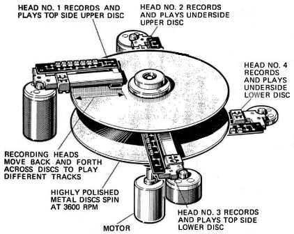 Stock Ampex HS-100 disc recorder included 2 discs. Had one record-playback-erase head per disc side. Video fields alternated between disk sides: Field 1 on Disc 1, top. Field 2 on Disc 1, bottom, etc. (Adaptation from Dunlop 111.) |
|
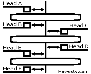
Probable Modification. Downlink operations required six tracks. (Specifications called for activity on five tracks, with the sixth track remaining unchanged.) The need for six tracks (five active at once) would have been beyond the HS-100's capacity. With four heads, the stock machine could only support four active tracks. Likely Westinghouse satisfied its requirements by adding a third disc and two more heads to the recorder. (Or maybe Westinghouse used two disc recorders.)
|
|
|
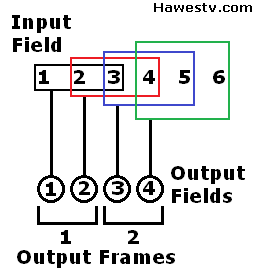
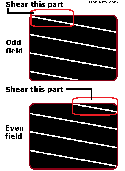
Disc operations. The recorder performed a different task on each track. On each successive disc rotation, this task switched by one operation. Playback (read) tasks occurred simultaneously and built the output video field. Each output field included two matching Moon fields and one that didn't match. For example, one even and two odd fields, or two even and one odd Moon fields. Normal field interlacing caused this mismatch. (Source of the mismatch: Standard odd fields began scanning at the top-left corner of the screen. Even fields began scanning a half line away, at the top-middle of the screen.) The disc recorder corrected the mismatch by introducing a brief delay. A half-line delay before starting the record head sheared off half a line. After the delay, the resulting Moon field matched the other two Moon fields. Leaving the non-matching field as-is would start scanning at the wrong screen location. A delay line in the disc recorder achieved the shearing effect. (Ennes 493, 495) The delay line was a passive, analog device of the quartz (not RCL) type. The delay before scanning was 31.5 microseconds. (Wood, 6)
|
|
Output from Downlink Disc Recorder, Example
(R= Red; B= Blue; G= Green)
(E= Even Field; O= Odd Field)
| Moon Fields → | R1 + B2 + G3 | B2 + G3 + R4 | G3 + R4 + B5 | R4 + B5 + G6 |
| O — E — O | E — O — E | O — E — O | E — O — E | |
| Field to Shear → | Shear B2 | Shear G3 | Shear R4 | Shear B5 |
|
Earth Fields (Output) → |
Field #1, RBG (O) | Field #2, RBG (E) | Field #3, RBG (O), | Field #4, RBG (E), |
|
Earth Frames (Output) → |
R-B-G, Frame #1 | R-B-G, Frame #2 | ||
About Disc Recorder Tables, Below
Disc from HS-100 recorder (Ampex 8) |
Video disc operation. The “Loading Moon Fields” tables below describe operation of the video disc. These tables derive from page 5-4, Figure 27 of this book: Apollo Color Television Subsystem Operation and Training Manual (by Westinghouse, or “WEC”). Each new disc rotation began immediately at the end of the previous rotation. (After Disc Rotation 6, the process at Disc Rotation 1 repeated, only with new data.) There was no time for heads to move radially. That is, “between disc rotations,” the six heads remained stationary. This mode of operation differed markedly from typical operation. Ennes (490) describes typical operation: One or more heads would step to a new track while another head recorded. Error in Record-Playback Sequence. This page corrects an error in the manual's disc color sequence. The book gave the sequence as R-G-B (red-green-blue). A private email from the late Stanley Lebar clearly and emphatically states that the sequence was R-B-G. The basis of this sequence was the color wheel that revolved before the Moon camera lens. This wheel adhered to Peter Goldmark's original CBS specifications. Not surprisingly, the Col-R-Tel scanning disc also followed Goldmark's R-B-G scanning order. RCA camera. According to the RCA camera manual, the RCA camera also followed the R-B-G sequence. (RCA 1-12) This sequence is why the same downlink equipment and program would work for both the WEC and RCA cameras. |
|
There was no way to specify which color field was the “first one” to come from the Moon. (Those who wish to view the R-G-B order from the WEC manual may use the color-change buttons. These buttons are beneath each table below.) First usable field. The disc had to contain three stored Moon fields. Otherwise, the disc couldn't play back enough data for one Earth field. The first four disc rotations recorded Moon fields into tracks 6, 1, 2, and 3. But what the disc played back was incomplete, and no usable Earth field resulted. Usable Earth fields didn't emerge from the system until Rotation 5. Each rotation took 16.7 milliseconds, so Rotation 5 wasn't complete until the 83-millisecond point. For that reason, there was a fleeting delay before the system could process the first Earth field. The R-B-G colors for each track are examples from Westinghouse. (Apollo Color Television Subsystem Operation and Training Manual, Figure 27, 5-4.) For instance, in the first table: “Track 1: Red-Even.” |
Repeating sequential-color Moon fields (left) to build simultaneous-color Earth fields (right) |
After the Disc RecorderAt Houston, the mooncam video underwent various electronic processes. The parallel output from the disc recorder fed to a standard color matrix (multiplexer) circuit. Next after the matrix came a proc (processing) amplifier. (Wetmore 20) NASA used stock equipment, probably by Grass Valley Group. (Wood 11) The matrix had three inputs, one for each color field signal. The matrix output standard NTSC signals. (Apollo Color Television Subsystem Operation and Training Manual 5-5, 5-6) These signals included...
|
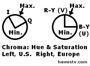
Phasor diagram: Chroma signals, NTSC (US, Mexico, Canada, Japan, etc.) and PAL TV (Australia, most of Europe, etc.) |
The proc amp provided...
- New, stable horizontal and vertical sync
- Stronger chroma signals (if necessary)
- The sound subcarrier, mixing Moon and Earth chatter.
During transmission worldwide via satellite, each country converted the NTSC (U.S.) TV signals to the local format.
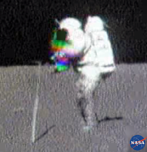
Color FringesFringe “Benefit.” Apollo Moon pictures often had color fringes. Such fringes are a flaw of field-sequential scanning. Fringes resulted from unmatched content within neighboring Moon video fields. See photo, right. A mismatch would occur anytime an astronaut moved quickly. The color fringes persisted even after conversion to simultaneous color television (NTSC/PAL/SECAM). What Viewers Saw. During motion sequences, such as an astronaut waving his arm, viewers noticed colored “trails.” For example, a moving arm would leave a momentary trail of arms: A red, a blue, and a green arm. A moment later, the “arms” would merge again, and appear as a single arm of natural color.
|
|
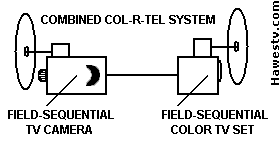
Reception on Earth Col-R-Tel SetEarth Col-R-Tel TVs could have picked up Moon Col-R-Tel pictures. This reception method would require no NTSC conversion. Consider that downlink stations included Conrac studio monitors that engineers had modified for field-sequential operation. These Col-R-Tel-like monitors could directly receive the Moon, field-sequential telecast. (Wood 11) |
|
Converters cancel. The Col-R-Tel converter and moon-downlink converter canceled each other. Thus without NTSC in between the converters, neither converter would be necessary. The TV pictures would probably come in fine.
|
Experiment. Someone could prove my statement about Col-R-Tel Moon pictures. The experiment involves transmitting Moon pictures on a standard TV carrier. Then the experimenter would reproduce the unconverted Moon signal. The picture would appear on a Col-R-Tel unit without hue and saturation conversion electronics. Both the Moon and Earth units would maintain their disc-sychronization systems. Cliff Benham has now performed this experiment, and it works! Cliff's homemade mooncam has reproduced color TV pictures on an original Col-R-Tel set. Since the camera pictures were field sequential, the Col-R-Tel converter worked barefoot! That is, without the adapter electronics. See... Homemade mooncam.
|
|
How the Standards Differed
Comparison. Below is a comparison of the Moon and Earth color standards vs. the CBS color standard. You can see how close Earth Col-R-Tel signals were to Moon Col-R-Tel signals. Note that both signals used the same vertical and horizontal frequencies. In both cases, the CBS system differed. This critical comparison underscores the statement that...
- The CBS system didn't go to the Moon.
- The CBS system couldn't lock a Moon TV signal.
Incidentally, this statement applies both before and after the downlink conversion. Either way, the CBS system was incompatible with Apollo color Moon pictures. On the other hand, Col-R-Tel borrowed extensively from both the CBS and NTSC color systems.
Standards Comparison
| Spec | Mooncam | Col-R-Tel | CBS | NTSC |
| Vertical sync | 60 Hz | 60 Hz |
144 Hz |
60 Hz |
| Horizontal sync | 15,734 Hz | 15,734 Hz | 29,160 Hz | 15,734 Hz |
| Horizontal lines | 525 | 525 | 405 | 525 |
| Color type | Field-sequential | Field-sequential | Field-sequential | Simultaneous |
| Color wheel wedges | 6 | 6 | 6 | 0 |
| Wheel scanning speed | 600 rpm | 600 rpm | 1,440 rpm | 0 |
| Scanning order at tube | RBG | RBG | RBG | Simultaneous |
| 3-color fields per second | 20 | 20 | 48 | 60 |
| 3-color frames per second | 10 | 10 | 24 | 30 |
| Flicker | Obvious | Obvious | Slight | Usually invisible |
| Underlying monochrome signal | NTSC | NTSC | CBS | NTSC |
Two-Color Mooncam
|
Simpler Conversion. If Stanley Lebar had chosen a two-color system, he could have avoided using the disc-based converter. Two-color, field-sequential pictures transmit at the same frequency as normal NTSC does. That is, 30 frames per second. In terms of speed, this rate is a huge improvement over the three-color, field-sequential system that Apollo actually used. Recall that the three-color pictures transmitted at only 10 frames per second. Still not live. Addition of NTSC signals such as the monochrome signal, chroma, and burst would still occur at the downlink. Also, Doppler correction would still be a requirement. Doppler correction involves a slight tape delay between two video recorders. This delay would remain. Yet two-color pictures could have been slightly closer to “live.” Why go with three colors, then? Because by Newtonian theory, a three-color system has a broader gamut than does a two-color system. That is, the three-color system can display pictures with more colors and better color fidelity. By the way, Edwin Land would contest this statement. (Land, Experiments; Retinex) About the same time as the color Apollo flights, the Spectrac® TV color converter reinforced Land's point. (Benrey 45-47) |

|
1971 Spectrac prototype, showing 2-color conver-sion. (Adaptation from Benrey 45) |
Resolution. Another disadvantage of the two-color system is that frames transmit at half resolution. There is no odd and even field for each color. Instead, for each color, only one field transmits. As with Spectrac, probably nobody would notice the difference. (Topping patent 1967) Which 2 colors? A typical two-color system displays orange and teal fields. A standard CRT makes the orange by turning on its red and green guns. To get teal, the CRT activates its blue and green guns. The result is much like the standard, NTSC chrominance I-signal. RCA engineers invented the I-signal because it is in the optimum color range for accurate flesh tones. The eye is more sensitive to flesh tones than to any other color. Two-Color Mode. Early color TVs included a two-color mode using the high frequencies of the I-signal. Today, few if any TV sets can decode this mode. (Color Television: Simplified Theory 44-45) One challenge for a two-color mooncam would be the U.S. flags that Apollo astronauts planted on the moon. Reproducing the white stripes and stars would be easy for such a two-color camera: Adding 100 percent orange and 100 percent teal produces white. But the camera's orange and teal axis is far away from either red or blue. What the camera would record would instead be dark red-orange and dark teal. From a reasonable distance, these colors would be fairly good stand-ins for red and blue. Take a look at our two-color flag (above). What do you think? For more about two-color television, click TV in two colors. |
Reference Links
- Abramson, Albert. The History of Television: 1942 to 1985. Jefferson, North Carolina: McFarland & Company, 2003.
- Ampex. “HS-100 Highband, Slow Motion VTR” Redwood City, California: Ampex Corporation, 1967. Press release including photos, 8 pp. Contacts: Gregg Perry (Redwood City), John B. Hatch (New York), & Carter G. Elliott (Chicago).
- Apollo TV and Communications Documentation: Mooncam articles, press releases, manuals, plans, etc.
- Benrey, Ronald M. “Add-On Converter Turns Your B&W TV into a Color Set” Popular Science, December 1971.
- Color Converter, Inc., Installation, Operating and Service Instructions for Col-R-Tel Converter. Columbia City, Indiana, n.d. (Probably 1955.)
- Dunlop, Richard. “Instant Replay: TV's Electronic Magic.” Popular Mechanics, November, 1971.
- Ennes, Harold E. Television Broadcasting: Tape and Disc Recording Systems. Indianapolis, IN: Howard W. Sams & Co., Inc., 1973. The section on the Ampex HS-100 disc recorder explains that its record-play heads were also erase heads. See pp. 482-555.
- Goldmark, Peter C. Color Television. U.S. patent 2,304,081, filed September 7, 1940 and issued December 8, 1942.
- Gray, Mark. Live From The Moon. DVD. Director, Mark Gray. Atlanta: Spacecraft Films, 2009.
- Grob, Bernard.
Basic Television: Principles and Servicing. 4th ed. New York: McGraw-HillBook Company, 1975.
Excellent, readable summary of NTSC (analog) television theory. Well-organized, topical chapters and a thoughtful index make data easy to find. One of the top television textbooks by one of the top television technical writers. - Hershey, Richard D. Color Television: Simplified Theory and Service Techniques. Editor, Donald G. Fink. Philadelphia" Philco Corporation, 1956.
- Johnson, NASA. “Astronaut Charles Duke During an
Apollo 16 Lunar Surface EVA” YouTube Video, 1:16. August 1, 2011. Accessed this site on July 29, 2019.
URL: https://www.youtube.com/watch?v=NiJ54Jj2rck
Provides a good example of the spurious color fringes that are an artifact of field-sequential scanning. Watch for the fringes whenever Astronaut Charlie Duke swings the hammer or makes a sudden move. - Land, Edwin H. “Experiments in Color Vision.” Scientific American 200, no. 5 (May, 1959): 84-99. http://www.jstor.org/stable/24940303
- Land, Edwin H. “The Retinex Theory of Color Vision.” Scientific American 237, no. 6 (December 1977): 108-128. https://www.jstor.org/stable/24953876
- Lebar, Stanley. “The Color War Goes to the
Moon.” Invention and technology (Summer, 1997): 52 and 54.
Stanley Lebar's story of the Westinghouse cameras. The late Mr. Lebar was Westinghouse's program manager for the mooncam project. Includes a photo of the color wheel. The layout of this wheel followed the layout of Peter Goldmark's color wheels for CBS. As on Goldmark's discs, color wedges curved away from the direction of disc travel. The curve of the wedges indicated the color sequence: Red—blue—green. - Lebar, Stanley. Private correspondence about Westinghouse's Apollo TV color cameras, emphasizing color scanning order, 11-23 through 25-2006.
- Lebar, Stanley. Private correspondence about Westinghouse and its development of color TV cameras for the Apollo Moon program, 2009.
- Lebar, Stanley & Charles P. Hoffman.
“TV Show of the Century: A Travelogue with No Atmosphere.” Baltimore: Westinghouse Technical
Information, 1967. Reprint of article in Electronics Magazine, New York: McGraw-Hill Education, March
6, 1967.
Technical details of Apollo monochrome camera circuit and Westinghouse SEC tube. Page 4 gives SEC tube image size as 0.5 inch. - Lindsay, Hamish. “A Technical Description
of Honeysuckle Creek During the Apollo Era.”; https://www.honeysucklecreek.net/. Accessed this site on June 24,
2019. URL: https://www.honeysucklecreek.net/station/technical.html
Subject: Downlink station equipment and operations in Australia, primarily Honeysuckle Creek, but also Tidbinbilla & Parkes. Site includes link to brief video of Stanley Lebar. Stan introduces Apollo monochrome & color mooncams & on-board video monitor. - Luckett, Hubert. “For $150 and a Bit of Work You Can Have Color Pictures on Your Present Television Set.” Popular Science, October 1955. Color pictures from a black-and-white television: Description of the Col-R-Tel kit by Color Converter, Inc. How to install it and set it up. The Col-R-Tel converter was a CBS-like color wheel and drive that operated off the TV's vertical sync. The Col-R-Tel adapter was an electronic circuit. Like the mooncams, this circuit was Spartan technology: Only the essentials. By discarding information, the adapter derived field sequential color from incoming simultaneous color signals. This clever circuit only required one chroma demodulator, and no delay line. The converted set required no convergence adjustments. Col-R-Tel was only for NTSC sets.
- Niemyer, L.L., Jr., “Apollo Color Television Camera,” media release, Westinghouse Defense and Space Center, Aerospace Division, Baltimore, MD, September 16, 1969. Presentation detailing the Apollo color cameras by a prominent WEC engineer. Mr. Niemyer delivered this white paper at the Electo-Optical Systems Design Conference in New York.
- RCA Government and Commercial Systems, Astro-Electronics Division. Ground-Controlled Television Assembly: Operation and Checkout Manual. Rev. ed. Princeton, New Jersey, 1972.
- RCA, Solid
State Division, Electro-Optics and Devices. The RCA Ultricon® and SIT Camera Tubes: RCA-Norbain
Electro-Optics Ltd. Seminar; Electro-Optics/Laser International '82 UK; Brighton 23-25 March 1982.
(Compilation includes “The silicon intensifier target tube: seeing in the dark” by G.A. Robinson.)
Lancaster, PA, 1982.
Technical details for SIT tube, possibly the same type tube as in mooncams on Apollo 15 through 17. See p. 10: Size of target is 0.5 x 0.38 inch (similar to target in WEC mooncam). Dimensions give a diagonal of 0.628 inch. Compare WEC SEC details at Lebar & Hoffman. - Russell, Sam. “Shooting the Apollo Moonwalks: A Recollection of How It Was Done.” http://www.hq.nasa.gov/alsj/Shooting-Moonwalks.pdf Access on June 13, 2019. The late Mr. Russell was the RCA Project Engineer. Covers Apollo 15-16-17 cameras.
- Spacecraft Films. “TV Transmission 33:59 GET.” Apollo 11: Men on the Moon. DVD set. No director. Los Angeles: 20th Century Fox, 2003. Specifies 12-second delay during downlink processing of color video from command module color TV camera.
- Spacecraft Films. “Probe & Drogue TV.” Apollo 11: Men on the Moon. DVD set. No director. Los Angeles: 20th Century Fox, 2003. Mentions 12-second delay during downlink conversion of field-sequential color video from command module camera.
- Topping, F.V. Color Converter for Black and White Television Sets. U.S. patent 3,535,435, filed May 22, 1967, and issued October 20, 1970. Topping's "Spectrac" system produces splendid, naturalistic color pictures on a black-and-white TV. With the assembled Spectrac kit, a two-color (red and cyan) filter fit over the TV screen. Viewers watched TV through a slow-moving, two-level, striped belt. The belt alternately obscured red or cyan stripes. The stripes were extremely narrow. They had the effect of turning the entire screen either red or cyan. Spectrac electronics sequentially switched the video: Only red video appeared when the screen was red. Conversely, only cyan video appeared when the screen was cyan. (By red or cyan video, we refer to intensity values for each color. That is, Spectrac combined saturation and brightness for each color, deriving intensity.) At normal viewing distances, neither the moving nor the stationary stripes were visible. The only artifact of the coloring process was a slight flicker in the picture. A display of the system enthralled vistors to the Chicago Consumer Electronic Show in 1971. A later Popular Science article described the system in detail, with technical drawings. Unfortunately Topping couldn't obtain adequate funding for manufacturing. He abandoned the Spectrac product.
- Westinghouse Defense and Space Center, Aerospace and Electronic Systems Division. Apollo Color Television Subsystem Operation and Training Manual. Baltimore: Westinghouse, 1971. Details of the camera, including schematics. Also probably the best source on the downlink video conversion system. See page 5-4, Figure 27.
- Westinghouse Defense and Space Center. “Westinghouse Builds Color TV Camera and 'Mini' Monitor for Apollo 10,” media release, Pittsburgh, PA, May 16, 1969. Quoting Westinghouse engineer Larkin L. Niemyer, Jr. (p. 3): “The wheel spins at 600 revolutions per minute and is divided into six sections so that the sequence of color filters as they pass in front of the tube during one revolution will be red, blue and green, red, blue and green.”
- Westinghouse Electric Corporation. "Westinghouse TV Cameras Bring Apollo Video from Liftoff to Moon Landscape," media release, Pittsburgh, PA, n.d. (Probably 1970.) See p. 11: Details the R-B-G (red-blue-green) sequence of colors on the Westinghouse color wheel: “As each color filter passes in front of the imaging tube, it collects all of the information on red colors and hues, then blue colors and green and then repeats the sequence again.”
- Wetmore, Warren C. “First Color TV from Space.” Aviation Week and Space Technology (May 26, 1969): 18-20. Concerns Apollo 10, the first mission with a color TV camera. Mentions the R-B-G sequence of colors on the Westinghouse mooncam's color wheel. Also brings up the counterweight that maintains tape tension in the tape loop between VTRs.
- Williamson-Labs. “The-Color Wheel-Camera: I B M-&-Sarkis Zartarian's-‘Com-Club.’” Williamson Labs. www.williamson-labs.com/480_hal.htm (retrieved 5-23-2013). Color wheel similarity: Compares Apollo & IBM color wheels. The article mistakenly names the Apollo color filters as cyan, yellow and magenta (CYM). These are the complements of the true colors. As Stanley Lebar and Cliff Benham explained to the author: In some photos, the Apollo filters appear to be CYM. This is because the filters are dichroic filters. Dichroic filters reflect the non-absorbed colors. The strongest rejected colors are the complements CYM.
- Wood, Bill. “Apollo Television.”;
www.hq.nasa.gov/alsj. Accessed this site on June 10, 2019. URL: https://www.hq.nasa.gov/alsj/ApolloTV-Acrobat5.pdf
Publication date: 2005.
Impeccable detail on both cameras and the downlink station. Includes facts and insights that don't appear elsewhere. By a former Apollo station engineer on the MSFN (Manned Space Flight Network).
General References About Mooncams
- Apollo Lunar TV—Its History and Development from Armstrong to Leonov. Links to many Apollo mooncam articles. From Stanley Lebar, program manager who oversaw mooncam development at WEC.
- NASA docs: More mooncam articles, manuals, and white papers. This is a more comprehensive collection than the above.
- Video short: Stan Lebar with the Apollo TV cameras. See Lindsay, Honeysuckle Creek
- Colin Mackellar, ed. “Honeysuckle Creek TV—Gene Cernan at
Shorty Crater” https://vimeo.com. Accessed this site on June 30, 2019. URL: ttps://vimeo.com/55766658
Publication date: December 17, 2012
Monochrome, 8mm movie off Conrac monitor. Engineers converted this monitor to display field-sequential color video from the Moon (apparently after Doppler correction). The movie shows flicker from the roriginal Moon transmission. One can also hear the Super-8 film advancing in the camera. At the Honeysuckle Creek downlink station, Ed von Renouard shot the original Super-8 film with a home movie camera. Colin Mackellar added the sound and painstakingly synchronized it to von Renouard's silent footage. The film documents Cernan's Apollo 17 moonwalk in December 1972.
Background Data: Space Program & Color TV
- Apollo & Soviet moon programs: Details of both programs.
- O'Neill, James E.
“Equipping Apollo For Color Television.” TV Technology Newsletter. Accessed this site on June 10, 2019.
URL: https://www.tvtechnology.com/news/equipping-apollo-for-color-television
Only site with data on CBS input on downlink station development. - Color TV history summary. Excellent brief on NTSC color TV system development (Ed Reitan)
- Detailed color TV history. NTSC TV development in more detail
- Mission summary from NASA
- Saturn V Moon rocket
- Smithsonian Saturn V exhibit
Alleged “Moon-Landing Hoax”
- Astronaut harassment to promote hoax believer's video
- Bad Astronomy.com. True story behind make-believe controversy.
- Clavius.org examines hoax claims. What hoax believers don't understand
- Photographs of Moon landing sites by NASA's LRO (Lunar Reconnaissance Orbiter).
- Public nuisance. Belligerence vs. national heroes
Go to Page: 1 2 3 Next Home
| HOME |
|
MOON COL-R-TEL, P. 1 |
|
MOON COL-R-TEL, P. 3 |
| MOON FAQ |
CONTENTS
- How the Downlink Converts Moon Signals
- Mooncam Process
- Compensating for Doppler Shift
- Conversion from Field-Sequential to NTSC
- Output from Downlink Disc Recorder, Example
- About Disc Recorder Tables, Below
- Loading Moon Fields 1 & 2
- Loading Moon Fields 3 & 4
- Building Earth Frame 1
- Color Fringes
- Reception on Earth Col-R-Tel Set
- How Standards Differ
- Standards Comparison
- Two-Color Mooncam
- Reference Links
- General References About Mooncams
- Background Data: Space Program & Color TV
- Alleged “Moon-Landing Hoax”
PHOTOS & DRAWINGS
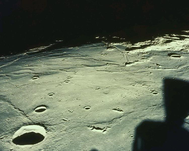
- Shadow of CSM (Moon photo)
- Moon Col-R-Tel
- WEC color mooncam
- Normal vs. Doppler-shifted sync
- Downlink Processes
- Moving Window
- HS-100 Disc Drive
- Disc recorder, 3 discs
- Video Interlacing
- Disc from HS-100
- From Moon video fields to Earth fields
- Building Earth fields
- Charlie Duke (Color Fringes)
- Combined Moon-Earth Col-R-Tel
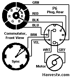
- Col-R-Tel Commutators
- Old Glory, in 2-color video
- Spectrac, 2-Color TV