Col-R-Tel 101
|
|
Tweet |

|
|
|
|
In Plain English
Col-R-What? So you aren't a geek. Yet Col-R-Tel still interests you. Okay! Here we go in plain English.
|
|
|
From the Station to Your Home
Let's start at the TV station. Tonight, the station is broadcasting your favorite color show. But the TV signal isn't really just one signal. It's several. These signals come to you over a “carrier frequency.” Inside the TV channel, many signals "modulate" or ride on this carrier. Each signal takes up part of the channel.
Luminance or Y. In the background, the regular black and white picture keeps on transmitting. Technicians call the black and white part the "luminance" signal. Really, luminance is a $64,000 term for brightness.
|
The color part. Towards the top of each channel is another carrier that we call a color subcarrier. All color (chroma and hue) signals modulate this subcarrier. Your TV paints hues over the monochrome picture. The color part of your show depends on two signals...
|
|
TV Signal Summary. So now, here's what we have: The normal TV signal carries brightness. The chroma signal carries color saturation data. Between lines, the TV station transmits a color sync signal that we call burst. Burst enables the TV set to reproduce natural hues.
Col-R-Tel from the Top Down
|
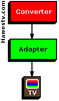
The Col-R-Tel device has two parts, a converter and an adapter. The converter includes most of Col-R-Tel's electromechanical parts, except for the controls. The adapter is the Col-R-Tel electronics and controls. The Converter is a powered color wheel with three transparent primary colors: Red, blue and green. You view a black and white TV set through this spinning wheel. The converter plugs into the Col-R-Tel adapter. The other side of the adapter connects inside your TV set. The adapter is an electronic circuit. It makes your TV set into a field-sequential color display. Field-sequential means that one hue at a time paints across the picture tube. The Adapter replaces each displayed video field with an equivalent color version. Switching takes place 60 times per second, in sync with the TV vertical signal. The adapter requires normal NTSC color programs. Col-R-Tel won't colorize monochrome broadcasts. |
|
Inside the Col-R-Tel Adapter
|
The Adapter (color processor box) synchronizes, detects and reproduces color TV pictures. Inside the adapter are most of the parts you'd find in a conventional color TV. Two parts are unique to Col-R-Tel: The hue selector and motor control. These “extra parts” allow for field-sequential conversion of NTSC signals. Our diagram shows the five major adapter parts. • Demodulator Block. The demodulator detects each chroma signal in turn: Red, blue, and then green. To do its job, the demodulator requires two inputs: (1) The reference signal that derives from the burst signal. This reference signal determines hue. (2) Chroma. Chroma is color saturation data for all colors. After the demodulator, the chroma signal separates and becomes “color difference signals.” |
|
• CRT Block. The demodulator input normally connects to the CRT cathode. The demodulator output normally connects to the CRT grid. At the grid, color difference signals add to and subtract from the luminance signal.
|
• Burst Block. The Col-R-Tel burst section synchronizes the color detector with the station's color signal. The burst circuit also allows you to adjust the picture hue to your liking. The burst block operates invisibly, between video lines. That's why the block connects to your TV's horizontal sync signal. This signal switches on the block at the end of a line. For a short time, the burst amplifier picks up color sync from the station. As the new scan line starts, the burst amplifier gates off. Meanwhile, the burst block passes three, synchronized hue references to the hue selector. • Hue Selector Block. The hue selector picks one of three hue references coming from the burst block. The selector discards the other two hues. Hue selection proceeds under control of TV vertical pulses from the Col-R-Tel commutator. At every vertical pulse, the hue selector switches the color reference signal to a new phase: R—B—G in sequence. |
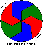 Col-R-Tel color wheel (derives from Goldmark disc)
|
• Motor Control Block. The motor control keeps the wheel in step with the station's vertical sync signal. The motor control also matches each color wedge with its picture field on the CRT. Through a commutator sensor, the motor control relates vertical pulses to disc wedge position. When the vertical pulse occurs, a new color wedge must move into place over the CRT. Normally, the controller allows the motor to operate at medium speed. When the disc is slow, the controller speeds up the motor. When the disc is fast, the controller slows down the motor.
Size Box: Optional Part
|
Size Box. If your TV picture is larger than the Col-R-Tel viewing window, you adjust the size box. The size box reduces the picture until the picture fits the window. Size reduction involves loading the yoke coils. Detailed Col-R-Tel TheoryFind in-depth theory on the main Col-R-Tel site and at Col-R-Tel FAQs. |
|
Page Directory
In Plain English From the Station to Your Home Col-R-Tel from the Top Down" Inside the Col-R-Tel Adapter Size Box: Optional Part Detailed Col-R-Tel Theory