Col-R-Tel Motor-Control Section
|
|
|
|
The first switch level has six contacts in a circular array. (Top-left switch level on the drawing, right.) The six contacts include two in parallel for each TV primary color. Why two per color? So that the disc can spin at half the speed. Whenever a wedge slides before the CRT, level one closes a circuit. Insulating material separates the contacts. Now imagine Col-R-Tel operating in sync with the TV station. Each video line period brings one of the six contacts into play. This contact and its partner across the disc connect to one color-select line. The circuit has three color-select lines, one for each additive primary color. In one disc rotation, each color-select line activates twice. When the active contact closes, it grounds one select line. The grounded circuit switches one of three color subcarrier phases to the demodulator. Each phase directs the chroma detector to demodulate one color signal (red, blue or green). The second switch level includes another six contacts. (Bottom-left switch level on the drawing, right.) Each contact applies a wedge-change signal to the motor control amplifier. This wedge-change signal is a 59.94-Hz sawtooth wave. An RC, low-pass network derives this wave from the vertical sync signal. During installation, you connect a blue wire to the TV's vertical output tube plate. This wire carries the vertical signal to the Col-R-Tel shaping network. With proper disc speed, all six wedge-change signals are the same. With improper disc speed, at least one signal may vary from the others. Speed correction is a frequent event. The reason for this situation is that the 60-Hz line drives the motor. Yet the motor must sync to the 59.94-Hz vertical signal. |
Connections to two-level Col-R-Tel commutator (not showing speed control or color phase selector) |
Motor Control AmplifierRotates wheel. The motor control amplifier accepts an input signal from the TV's vertical output plate. On the way to the motor control amplifier, the signal encounters a low-pass, R/C filter. (See the diagram, right.) The filter converts the signal to sawtooth waves. Next, the wheel commutator gates the signal and passes it to an error preamplifier. At the preamplifier, the signal drives the two halves of the motor control amplifier. Each plate of this amplifier connects to one end of a transformer primary. The secondary couples 60 Hz AC into the two plates. The plates are 180 degrees out of phase with one another. The transformer primary center tap provides B+ power to the amplifier plates and cathode. The transformer secondary is in series with the motor speed control pot, motor field and AC line. With no error signal, the coil poses almost zero voltage drop. With an error signal, the secondary voltage aids or opposes the AC voltage across the motor field. Disc Motor |
Col-R-Tel RC shaping network between vertical sync and motor control |
| Col-R-Tel Motor Specs | |
| Manufacturer | Howard Industries |
| Model | 2815-43 |
| Power | 115 volts AC at 1.5 ampere |
| Type | 1/25 horsepower, four-pole, shaded induction motor |
| Unloaded speed | 1750 rpm |
| Comment | Runs hot. |
Speed converter. Through the laws of unequal pulleys, the motor develops enough torque to spin the disc. The wheel pulley (2-7/8 inches ID) is much larger than the motor pulley (1 inch ID). According to Cliff, the motor-to-wheel pulley ratio isn't quite 1:2.875. Cliff estimates that the design allows about 8 rpm for slippage. To develop the normal disc speed of 600 rpm, the motor must turn at 1725 rpm. That is...
(600 * 2.875) = 1725
[ (1750 - 1725) / 2.875 ] = 8.7 Hz (rounded)
Sensor
Composite. The sensor on the block diagram is actually the commutator. As we said above, this commutator is a composite. It includes the 12 switch contacts inside the commutator. six contacts sync the disc to the TV station's vertical signal. The remaining six contacts each select one of three color subcarrier phases: Red, blue or green. The picture tube illuminates one disc (wheel) wedge at a time. The commutator mounts mechanically to the color wheel. For this reason, the commutator always selects the phase that corresponds to the illuminated disc wedge.
Disc
|
The color wheel. The Col-R-Tel disc (right) looks a lot like the CBS disc. Both discs have six transparent color wedges. The wedges follow the order R-B-G-R-B-G. On both discs, the bottoms of the color wedges twist 30 degrees (one clock number). Discs with the characteristic twist can scan larger picture tubes than can discs with no twist. From the viewer's position, both discs rotate clockwise. Rotation. The Col-R-Tel disc rotates at 600 rpm. The CBS system used 1,440 rpm, because CBS broadcast 144 fields per second. On the other hand, our NTSC TV system broadcasts 60 fields per second. Col-R-Tel has to maintain compatibility with the NTSC field rate. Col-R-Tel's 600 rpm disc speed is approximate. Your set's 59.94 Hz vertical frequency determines the exact disc speed. This speed is somewhere around 599.4 rpm. Col-R-Tel's disc measures 31 inches across. The disc can convert pictures up to 14 inches across. If your picture is larger, you reduce it with Col-R-Tel's size control. |
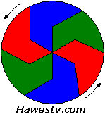
Col-R-Tel & CBS color wheel |
Go to Page: 1 2 3 4 5 6 7 8 9 Next
COL-R-TEL CONTENTS
- OVERVIEW
- DEMODULATOR SECTION
- BURST SECTION
- MOTOR CONTROL SECTION
- Wheel commutator
- Motor control amp
- Disc Motor
- Motor Spec Table
- Sensor
- Color wheel
- SIZE CONTROL SECTION
- PERFORMANCE COMPARISON
- DRAWBACKS
- OTHER COLOR ADAPTERS
- COL-R-TEL ENHANCEMENTS
- COLOR WHEEL TV FAQ
- HOW TO WIND DELAY LINES
- Back to top
|
Copyright © 2005 by James T. Hawes. All rights reserved.
•URL: http://www.hawestv.com/mtv_color/colrtel_motorBlock.htm
•Webmaster: James T. Hawes
|