Simplicity Itself
Keep it simple, but make it better!
1955 in color and black and white. Col-R-Tel models 101-1 and 101-2 are simplicity itself. And they deliver elegant color to a black-and-white world. All for $150 and two hours of work. In fact, after you install a few sets, the job time drops to about a half hour. In 1955, who could ask for anything more?
Nobody. But in 1956, along comes Colordaptor. The Menlo Park, California Colordaptor is a challenger to reckon with. Color Converter, Inc.'s Col-R-Tel is easier to install. And besides, you have to build Colordaptor. Plus, Colordaptor is a more complex circuit. Yet Colordaptor has an ace in the hole: It works on 1956 black-and-white sets. Col-R-Tel only seems to work properly on vintage sets, sets from before 1954.
|
|
|
Clear picture. Also, Colordaptor raises the bar on picture quality, at least theoretically. Why? Because Colordaptor has a delay line. The delay line moves the monochrome picture or luminance directly under the corresponding color picture. Result: Assuming that you follow the instructions, a far clearer picture.
Land of the golden slide rule. Ah, but time doesn't stand still at Columbia City, Indiana, headquarters of Color Converter, Inc. Color Converter's hoosier engineers are 52.4 percent cleverer than normal technical personnel. You'd expect as much, since these engineers operate in the shadow of Purdue University. Purdue is one of the original television research institutions. The engineers pour on the coffee, sharpen their drafting pencils, and roll up their sleeves. With a slip of the slide rule, they soon have an answer to Colordaptor. In true Col-R-Tel fashion, this answer is simple, elegant and just on the mortal side of perfection.
Problem: Weak Chroma
Narrowband IF. The first problem is this: Col-R-Tel models 101-1 and 101-2 depend on the TV to supply a wide bandwidth video signal. Most black-and-white TVs from 1954 on contain narrowband IF strips or low-pass filters. A wide passband is a disadvantage, because it picks up the chroma signal. In a black-and-white TV, the chroma signal interferes with the monochrome signal. Today, comb filters take care of this problem. Back in 1955, comb filters are an engineering fantasy. The narrowband IF or low-pass filter has to do.
Narrow & Wide IFs. Unfortunately, the resulting passband seems to attenuate chroma and burst signals that Col-R-Tel depends on. Col-R-Tel picks up its signal at the CRT cathode. Yet the signal that arrives there is often too weak to be useful. For color adapters, it's not a fair world.
Remedy: Move the input line
|
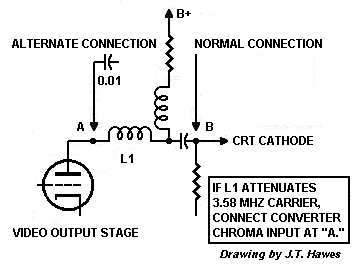
Engineering ingenuity to the rescue. Col-R-Tel engineers discover that the problem actually isn't the IF strip or low-pass filters. The real problem? An inductive peaker in the final video amplifier's plate circuit. See the schematic. After the peaker, some TVs provide an excellent chroma signal. This is the traditional Col-R-Tel connection, where the last video plate meets the CRT cathode. On other TVs, the signal there contains attenuated highs. With these TVs, the trick is to move the yellow Col-R-Tel input wire. The new connection is through a 0.01 uF capacitor. Connect the capacitor to the plate side of the inducive peaker. The capacitor isolates Col-R-Tel from high voltage DC at the plate. Color Converter, Inc. also adds an LC series filter between the TV and the Col-R-Tel coupling capacitor. This filter reduces video smearing. Unlike Colordaptor, Col-R-Tel still requires no added stage of amplification. The lack of one maintains Col-R-Tel's lead as the more efficient circuit. |
|
Problem: Color Superimposition
Col-R-Tel's delay line. Another Colordaptor advantage is its delay line. Installing the delay line before the final luminance amplifier takes a little extra time. But the 1.3 uS delay lines up the color and monochrome pictures. The result is a nice, clear, snappy image. The original Col-R-Tel circuit operates without a delay line. Col-R-Tel's misalignment is slight, but persnickety viewers can see it.
Remedy: Add a Delay Line
|
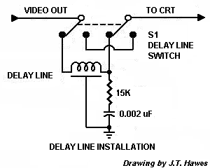
Shorter delay. Col-R-Tel has to come up with its own delay line. And Col-R-Tel engineers do exactly that. Col-R-Tel doesn't process the chroma as much as Colordaptor does. Apparently for this reason, the Col-R-Tel delay only needs to be 800 nanoseconds. Incidentally, the shorter delay line requirement points out another triumph for the Indiana engineers: As Cliff Benham's tests prove, Col-R-Tel has a flatter, wider color bandwidth than Colordaptor does. See the delay line schematic. The Col-R-Tel delay line reduces contrast. During monochrome reception, you can deactivate the line by switching it out of the circuit. A 15 K resistor and 0.002 uF capacitor load the delay line. Loading reduces reflections (ghosts). Some receivers require slightly different loading values. Determine these values experimentally. For awhile in the late 1950's, Color Converter Inc. sells its 800 nanosecond delay line for Col-R-Tel. With the delay line and new video pickup, Col-R-Tel's picture is a sight to behold. |
|
Commercial delay line sources. For those who'd like to upgrade their Col-R-Tel to the world-class standards of Columbia City, Indiana's foremost engineers...
| Delay Line Vendors | ||||
| Vendor | RCD Components | Rhombus Industries | Toko, Inc. | Faraday Tech |
| Web site | RCD-Comp.com | Rhombus-Ind.com | Toko.com | Faradaytech.co.uk |
Toko. Cliff Benham notes that TOKO makes delay lines that might work with a solid-state TV. Cliff is interested in the part number H318LNKN2601WAE. This part is the TOKO's 400 nS, 1.2K ohm delay line. Cliff says that the price is only some $3.00. He mentions that a builder could cascade two lines to achieve an 800 nS delay.
Faraday Technology delay lines also interest Cliff. Apparently the price is reasonable.
Dallas Semiconductor offers semiconductor delay lines in dual inline packages (DIP). The 200 nS lines should be easy to cascade. Each IC includes three 200 nS delays. These lines require a 50-ohm source. (Unfortunately, this impedance is quite low for a tube application.) Digikey stocks the Dallas part. For the datasheet, see Dallas delay line.
Problem: Not enough high frequencies
|
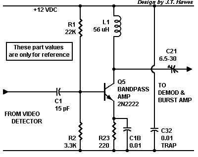
Add a preamplifier. One of Col-R-Tel's weaknesses is that it has no true chroma bandpass amplifier. The demodulator must also serve as bandpass amplifier, saturation control and equalizer. This circuit is a master of all trades, but it excels at no one task. The circuit compromises are just too great. To ease the demodulator's burden, you can add an equalized preselector. This new stage is a bandpass amplifier that emphasizes high frequencies. Monochrome TV sets usually attenuate these high frequencies. Without these color frequencies between 3 and 4 MHz, Col-R-Tel can't operate. That's why Colordaptor engineers added a preselector. I've adapted this simple Colordaptor preselector to transistors. The circuit should go something like my nearby drawing. Have a look at my experimental schematic... Remedy: Add a High-frequency boosterThe parts are available from Mouser Electronics. Notice peaking coil L1 in transistor Q1's collector circuit. The reactance of this coil increases with frequency. At 3.58 MHz, the reactance is 1260 ohms. The emitter decoupling capacitor has a similar effect. Its reactance decreases with increasing frequency. You could use the capacitor alone, and just replace coil L1 with a 1.2K resistor. Yet if you make this replacement, the high-pass effect won't be as pronounced as with L1 in the circuit. |
|
To increase input impedance, you can change the bias network. For example, replace resistors R1 and R2 with a 470K resistor to Vcc. The new circuit probably won't be as stable as the original, but the impedance will be higher. By changing the 470K value, you achieve different amounts of boost.
Connection point. The connection point in the circuit is very important. This preamplifier inverts the chroma signal. If inserting this preamplifier makes your colors invert (purple instead of green, etc.), you have the preamplifier connected wrong. Move the connection point down one stage. Now the video should be okay.
Ringing. If the booster rings, then you're producing too much boost. Ringing will show up as a distortion of fine picture details. You can dampen the ringing by soldering a resistor in series with the inductor. Determine the correct value experimentally. I'd guess that the correct value is somewhere between 100 and 1,200 ohms.
Problem: Lack of a matrix
Single demodulator. In Col-R-Tel, a switch selects one chroma signal and sends it to a single demodulator. Colordaptor works the same way. The switch distinguishes these circuits from standard television color detectors. While this approach saves gates, it causes various reproduction problems. One problem is that the demodulator has the same gain for all colors. Yet the transmitter doesn't modulate the three colors equally. Reproduction fidelity depends on the receiver's ability to equalize the transmitter's signal.
Color emphasis. Normal TV receivers have similar demodulators, but emphasize one color over the other by matrixing the output. If the demodulation angles are different than 90 degrees, the matrix also corrects the angles. In many sets, the matrix adds and inverts blue and red signals to reconstruct green. Col-R-Tel and Colordaptor lack the second demodulator, and can't perform any of these matrix corrections.
Jay Stanley's color adapter solves the matrixing problem by using a more elaborate circuit. Stanley's adapter includes the standard two demodulators and a typical matrix circuit. In Stanley's adapter, the RGB field-sequential switch appears after demodulation and matrixing. Still, we can't easily double the number of tubes in Col-R-Tel. Stanley's circuit is out of reach.
Remedy: Add variable gain
Simulated matrix. Maybe a more practical way to go is to simulate a matrix. A builder could add a third tier to the Col-R-Tel switch. The third level would have six contacts, one for each color wedge (two wedges per color). Each contact would switch a resistor into the demodulator stage. This resistor could be in the cathode or plate circuit. Another spot for the resistor would be between the plate and ground. At the switch, a small-value capacitor would bypass switch transients to ground.
Without adding a switch. To switch ground, you might not need a third commutator switch tier. Col-R-Tel already provides a tier that switches ground. The only issue is whether the tier can handle the additional current.
The effect. The new resistors would vary stage gain. The visible effect would be a color saturation change that varies by color: Sort of a field-sequential matrix. And exactly what we want.
Other Enhancements We'd Like
On my wish list for Col-R-Tel enhancements are several more ideas...
- A DC-restorer to reconstitute the missing low frequencies. Notice that Col-R-Tel couples to the CRT grid through a capacitor. Another capacitor connects the detector to the demodulator. There is no circuit that clamps the color level to the sync. Certainly we could add such a circuit. Such a circuit might free the viewer from many saturation readjustments.
- Automatic color control (ACC). While we're on the subject of saturation adjustments, how about automatic saturation? Contemporary NTSC sets include automatic color control. The idea is the same as an automatic level control in most radio receivers. Signal strength at a later stage controls the bias of an earlier stage. Since Col-R-Tel's demodulator is also its chroma amplifier, ACC would be difficult. Still, we could add a chroma amplifier. We've already mentioned that idea. Why not control the gain of this new amplifier with the CRT output signal?
- Automatic hue control. Many color textbooks call this "automatic tint control" (ATC). A basic ATC system shifts the red color demodulation angle toward orange. Sometimes the ATC system also shifts the blue demod angle toward cyan. The idea is to increase the chances of correct fleshtone reproduction. Flesh tones for all races include a lot of orange. Viewers also tend to be most sensitive to improper colors in human faces. If we reproduce more oranges, then faces look right, and we satisfy viewers more often. Satisfactory colors mean fewer hue adjustments. Oddly enough, the rest of the spectrum is now a little out of whack. Almost nobody notices.
Go to Page: 1 2 3 4 5 6 7 8 9 Return