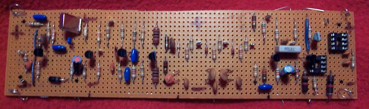
 First breadboard for solid-state Col-R-Tel. L-R:
| •Burst amp | •Xtal amp | •Limiter | •Phase-splitter | •Phase selector |
| •Chroma demodulator | •Output opto driver | •Output opto | •Input opto driver | •Input opto |
If Col-R-Tel were solid state, the circuit might look something like the schematics that follow. For those who wish to build a solid-state color adapter, please take my schematics as I intend them. These are not tested circuits, but an illustration. Purely for illustration purposes, I include likely parts values. I've never built the circuits below, but I've experimented with similar circuits. Undoubtedly solid-state Col-R-Tel circuits would require much tweaking before you'd see color pictures.
What I've done here is to take you to the first stage. These circuits exist to satisfy curiosity. They answer the "what if..." question at the top of this page. Along the way, I provide a little theory on each circuit.
Some of these circuits might work, and some might not. Still, even a vintage Col-R-Tel wouldn't convert today's monochrome TVs to color. I've updated some of the circuits, but not all. In a few places, I've also suggested modern parts, such as a triac or an optocoupler. The rest of the adapter is pretty close to the original, but with transistors instead of tubes. I've adjusted voltages, currents and bias to match the solid-state devices. For instance, the original Col-R-Tel operated off 190 volts (300 before the filter). My transistor schematics operate off 12 volts (18 volts before the regulator).
To match the simplicity and serviceablility of the original, I've designed with mostly discrete devices. Also, the coils and capacitors are what I found in a catalog search. The original parts are obsolete, and I've attempted to locate reasonable replacements.
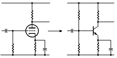 Transistorizing a triode tube amplifier
Circuit part numbers. Where possible, I've matched circuit part numbers to the original numbering system. The idea is to pair a part number to a part function. That way, I convey an idea of how my transistorizing process proceeds. Many times, a resistor, capacitor or coil matches a functionally similar part from the original circuit. In other cases, I've found a part number in the same vicinity and reassigned it. Where I can't find a similar part, or don't have enough numbers, I assign new numbers starting in the 100s. That rule applies to passive parts. With active parts such as transistors and ICs, I renumber starting from one.
|
▲ WARNING. Anyone who builds these circuits does so at his own risk. I take no responsibility for your success or failure. If you injure yourself, damage your favorite oscilloscope or burn your house down, you pay the damages. If you aren't an advanced builder and experimenter, don't even attempt this project. If you can't improve on these schematics, then you aren't ready to start building. Don't connect anything to a television set. The set might not have an isolated power supply. You could suffer a fatal shock. That would be a lesson that you'd never remember. But your family would never forget. From time to time, I will update and attempt to improve these drawings. I will make changes without notice. • NOTICE. If you'd like to contribute ideas or suggestions, email me. Submitted ideas and suggestions become the property of Hawes Mechanical Television Archive. I try to mention the source of anything I use. |
Go to Page: 1 2 3 4 5 6 7 Next