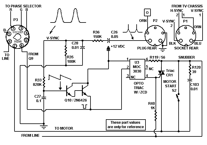
Motor-Control CircuitSawtooth Forming Network. The TV vertical sync controls the scanning wheel speed. A coil couples the vertical sync into our color converter circuit. Sharp pulses from the vertical output transistor collector pass through R/C network C26, R36, C28 and R35. These parts produce a low-going sawtooth wave and couple the wave. A further filtering network R33 / C27 stretches the wave. The wave enters the base of Darlington Q10.
|
|||
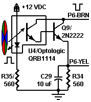
At the start of each color wedge is a tiny reflective spot. When the wedge comes into position, an infrared LED shines on the reflective spot. A coating on the phototransistor keeps CRT and viewing room light from interfering with the phototransistor.
Optodetector U4 is a normally off device. Most of the time, then, the phototransistor output is high. Upon light detection though, infrared optodetector U4 switches on and outputs a low pulse. Transistor Q9 forms a Darlington circuit with the optodetector. The Darlington can handle more current than the sensor alone can. The Darlington output is in phase with the sensor output. The low pulse is a gating pulse for sampling triac driver Q10, another Darlington. Electrically, transistor Q9 is in series with the emitter circuit of Darlington Q10. As Q9 pulses low, it conducts and provides a ground path for Darlington Q10.
|
Sampling Darlington Q10. Pulses from Q9 have another purpose, too. These low pulses cause Darlington Q10 to sample the vertical sync sawtooth pulse. Darlington Q10 replaces V5B, a 12BH7 tube in the original Col-R-Tel circuit. During a color wedge transition, the Q9 collector goes low. The low pulse excites the Q10 emitter, gating Q10 on. While the Darlington is on, it amplifies a sample of the vertical sawtooth. With the Darlington on, the sawtooth determines the output voltage. During wedges, Q9 remains high, gating Q10 off. With Q10 off, then, the Q9 voltage determines Q10 output voltage. Q10 passes its samples on to the DC or input side of opto triac U5. While sampling, Darlington Q10 detects three important states: The sawtooth on the base is high, low, or somewhere in between. |
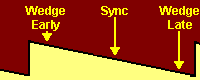
Optodetector U4 samples three states of the wedge waveform |
- If the disc wedge is early, the sawtooth is high. Q10 output goes low.
- With perfect disc sync, the normal state, the sawtooth is at some medium voltage. Q10 output is somewhere between 12 volts and zero volts.
- If the disc wedge is late, the sawtooth is low. Q10 output goes high.
LED Drive. Despite the high impedance of its inputs, Darlington Q10 develops enough current to drive an LED. The inverted output of Q10 drives opto U5's internal LED. Opto U5 couples to motor-control triac CR1.
- A low voltage (wedge-early signal) on the Q10 collector turns the LED off.
- A medium voltage (wedge-sync signal) at the Q10 collector turns the LED halfway on.
- A high voltage (wedge-late signal) at the Q10 collector turns the LED fully on.
Motor Voltage Control Triac CR1. Triac CR1 is a pulse-width modulator. CR1 connects in series with the color wheel motor. The triac circuit replaces V6, a 6BL7 dual triode tube in the original Col-R-Tel circuit. The triac also replaces T3, the Col-R-Tel motor control transformer. The triac gate voltage varies with signals from Q10. The triac output voltage varies with the gate voltage and the line AC. Like the tube in the original Col-R-Tel circuit, the triac has two halves. Each half of the triac is an SCR that interacts with one alternation of the power AC waveform. As triac CR1's input voltage varies, the triac's resistance changes. This resistance change increases or decreases the voltage drop across the motor...
- If the disc wedge is early, then the motor speed is too fast. The CR1 input voltage is low. Triac CR1 increases its resistance and reduces current flow to the motor. The motor slows down.
- When the wheel is in sync, the voltage on triac CR1's gate is moderate. Triac CR1 maintains its resistance and allows current to flow to the motor.
- If disc wedge is late, then the motor speed is too slow. The CR1 input voltage is high. Triac CR1 decreases its resistance and increases current flow to the motor. The motor speeds up.
Go to Page: 1 2 3 4 5 6 7