The R-Y phase comes directly off the collector of phase splitter Q4. On a vectorscope, the R-Y reference vector appears at 12 o'clock. (Of course, the hue control can alter the position of this vector.)
About Q4. In the latest version of this circuit, device Q4 is a Fairchild 2N6426 Darlington. Despite its low-impedance load, this device provides a high input impedance to the previous stage. The previous stage is a limiter, and it needs all the gain it can muster. For limiter Q3, the phase shifter's high impedance is a very light load. The Darlington fits in the same TO-92 package as the 2N2222A transistor that it replaces.
Not chroma. Note that Q4's three output phases aren't chroma signals. Instead, these signals are continuous wave, unmodulated subcarriers. They carry no pictorial data. Also, Col-R-Tel G-Y and B-Y reference phases don't correspond to NTSC G-Y and B-Y reference phases. Col-R-Tel R-Y corresponds to NTSC R-Y when the hue control causes a 90-degree lag. The 90-degree setting should be near the middle of the control's rotation. The hue control setting is a matter of visual preference, rather than phase matching.
Phase lag networks. Two R-C phase-lag networks connect across Darlington Q4. The output voltages from these networks represent the B-Y and G-Y subcarrier phases. If you compare these phase shifters with the Q2 hue control circuit, you'll notice similarities. Of course, the phase shifter is variable, and Q4 uses fixed shifters. Also notice that the two Q4 shifter circuits are upside-down from each other. That's because one filter shifts the R-Y reference. The other filter shifts negative R-Y.
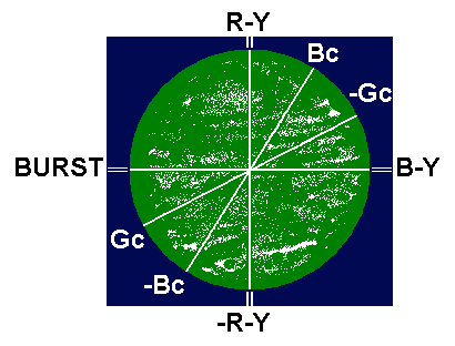
Above is a vectorscope view of the Col-R-Tel spectrum. "Gc"
indicates Col-R-Tel G-Y. "Bc" indicates Col-R-Tel B-Y. Col-R-Tel R-Y matches NTSC R-Y.
Cost savings. In the transistor Col-R-Tel, Darlington Q4 replaces transformer L2 from the original circuit. Transformer L2 is probably a proprietary part, and might be difficult to obtain today. Darlington Q4 can is a Fairchild 2N6246 that you can obtain from Mouser. The cost, time and space savings are significant.
Go to Page: 1 2 3 4 5 6 7 Next