Gun-Drive Circuit
|
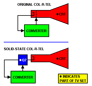
New insertion point. Recall that the original adapter picks up inputs and inserts outputs at the CRT. Solid-state Col-R-Tel moves back from the CRT by one stage. Opto isolator U1. Transistor Q7 is the TV set's electron gun driver. For the Q7 function, the original Col-R-Tel adapter uses a 12BH7 triode. Instead of adding our own Q7, we take a shortcut: Opto isolator U1 applies the color difference signal to the TV set's Q7. See U1 and Q7 on our schematic, below. The opto also isolates viewers and the adapter from power line hazards. Opto U1 and its twin U2 are high-speed devices. |
Transistor Q7. The new approach sidesteps the requirement for a costly, high-voltage transistor. The opto inverts, so the signal maintains the proper phase. A positive color difference signal enters transistor Q7. Transistor Q7 again inverts this signal, and the CRT gun receives negative drive. This phase follows official Col-R-Tel specifications for cathode drive.
More detail. Below is a more detailed discussion of the circuit. Throughout this discussion, I refer to a typical TV circuit. Some TVs use a slightly different circuit. Installation must allow for circuit differences.
Col-R-Tel Output Side
Y-C Mixing. At transistor Q7, in-phase luminance (Y) and chrominance (C) signals mix. The picture tube reproduces this combined signal in black and white. The picture tube and color wheel convert the summed signal to a color picture.
Color difference signal. The low-going color difference signal from demodulator Q5 enters the base of transistor Q6. Transistor Q6 maintains the signal phase and modulates the LED inside opto isolator U1. The LED now carries the chroma signal as a flickering light beam. This beam excites the photodiode inside opto U1. The photodiode controls the U1 output transistor.
Phase inversion. The photodiode signal is low-going. It is out of phase with the luminance signal at transistor Q7's base. The opto output transistor inverts the chroma signal. Capacitor C22 is the injection point. Here, the chrominance is back in phase with the luminance signal. Capacitor C22 carries the chroma to the base of power transistor Q7.
Col-R-Tel Input Side
Opto isolator U2. Transistor Q7's collector drives emitter follower Q8. The Q8 follower circuit's characteristic high impedance avoids loading Q7. Q8 drives the LED inside opto isolator U2. Neither transistor Q8 nor the opto invert. Opto U2's output splits into two paths. One path provides the chrominance signal to demodulator Q5. The second path furnishes the color burst to burst amplifier Q1. The chroma and burst input phases match the Q7 output phase. The signal phases also match the phases in the original Col-R-Tel.
TV-supplied power. Note the power arrangement for optos U1 and U2. Half of each chip obtains power from our adapter power supply. This is the part of the chip that connects to Col-R-Tel. The other half of the chip runs on 12-volt power from the TV set. Transistor Q8 also draws TV power. Most TV sets operate the video stages off a scan-derived power supply. Typical operating voltages are 12, 18, 20, 24 and 30 VDC. One of these voltage supplies should provide ample power for our circuits.
|
▲ WARNING. You can't power either opto circuit with more than 12 volts. If the supply exceeds 12 volts, use a voltage divider to provide the necessary 12 volts. Greater voltages damage the opto and cause a fire hazard. If your TV sources less than 12 volts, use another TV set. |
Increase resistors. Where devices connect to TV power, resistor values and wattages might vary. The values depend on the TV's power supply voltage. If the TV power voltage is over 12 VDC, you must increase the values of resistors in the Q8, U1 and U2 circuits. Otherwise, these circuits will likely suffer damage. Here are some helpful guidelines...
- Most opto LEDs can't handle voltages over 1.5 to 2 VDC.
- Check the datasheet for the devices that you use. Stay within limits.
- About 0.4 mA average should flow in the opto U1 collector circuit.
- Transistor Q8 should draw an average of 6 mA.
- The LED series resistor formula is: R = (Vcc - VLED) / ILED.
- In the formula above, Vcc is the power voltage. VLED and ILED are the LED operating voltage and current.
Connections to the TV set. Original Col-R-Tel installation instructions specify several connections to the TV set...
-
Field-sequential converter box
- A black wire to the TV chassis: This wire supplies the Col-R-Tel ground reference.
- An orange wire at the horizontal output tube: This wire carries horizontal sync pulses to the Col-R-Tel burst amplifier.
- A yellow wire at the picture tube cathode: This wire is the chroma and burst takeoff point.
- A green wire at the picture tube cathode: This wire is the chroma and burst takeoff point.
- A blue wire at the picture tube cathode: This wire brings the vertical output pulse to the motor speed control circuit. Size-Control box
- Another black wire: This wire connects the size control circuit to the low-potential side of the horizontal yoke coil.
- A red wire: This wire connects the size control circuit to the high-potential side of the horizontal yoke coil.
- Another yellow wire: This wire connects the size control circuit to one side of the vertical yoke coil.
- Another green wire: This wire connects the size control circuit to the other side of the vertical yoke coil.
Converter inputs & outputs. You can ignore the size-control box connections above. Notice that the yellow and green connections between the original Col-R-Tel converter and the TV. These wires are the Col-R-Tel inputs and outputs. Our solid-state Col-R-Tel also connects to the TV through yellow and green wires. Also, both the input and output go to the cathode drive transistor. We'll see if that setup works. For the time being, I've made no provisions for grid-drive TV sets.
Development Options
Changes for CRT grid drive. More traditional experimenters can reroute the output wiring to the CRT grid circuit. Grid drive might require inverting the RC phase connections at RGB phase splitter Q4. (Affected parts: R12/C13 and R11/C17.) You'll also need to add a grid-drive transistor. I suggest that you maintain isolation from the set by controlling the new transistor through an opto. The grid-drive circuit will resemble Q6, U1 and Q7 above.
Alternate power source. Another option for a voltage source is a rectified winding on the flyback. For this purpose, you might even rectify the output of the burst gate winding. The burst gate must receive the unrectified pulse, though. With all power coming from the TV set, you might eliminate the optos at Q7. In that case, you must insulate the Col-R-Tel case! Also, take care not to overheat the TV power supply. This supply must have enough excess power capacity to handle the added circuits.
About the optos. The optos in my circuit might seem like complexity for its own sake. Still, the optos are worthwhile, since they protect you and your circuit from shorts. Without isolation, I suggest avoiding a hot chassis TV. If you don't know that your set is safe, then you should skip this project.
Calling all video experimenters: Please tell me what you've tried, and what works!
Go to Page: 1 2 3 4 5 6 7 Next