Chrominance Demodulator Q5
Tuned circuit. For maximum signal, tank circuit C2/L6 resonates at 3.58 MHz. The bandwidth of this input filter is 1 MHz. The filter accepts both sidebands of the AM, supressed-carrier chroma signal. The complete signal covers the band from 3.08 MHz to 4.08 MHz.
|
|
Reference. Meanwhile, the phase selector sends one of three subcarrier reference phases to the demodulator. This phase sets the color that the demodulator detects, and the picture tube reproduces: Red, green or blue. High level. Unlike the chroma signal, the subcarrier reference signal is a fairly high-level signal. Since the subcarrier reference is unmodulated, it is also a narrowband signal. Components L4 and C21 tune this signal to resonance at 3.58 MHz. |
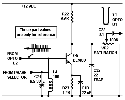
Sidebands. As I said, the input chroma signal comes from the CRT cathode (gun). To excite the cathode, a signal must be negative-going. That is, the chroma has positive burst and inverted sidebands. The lower sideband is the one that we want. At the demodulator, this sideband is positive. The demodulator clips off the negative-going sideband. Yet this time, the negative-going sideband is actually the unwanted, upper sideband.
Mixing. The subcarrier signal enters the Q5 base. The subcarrier phase and chrominance signal mix at transistor Q5. The result is a one-color signal of proper amplitude and phase.
Demodulator theory. The subcarrier reference is the bias source for the detection process. Demodulator Q5 is a class-B amplifier, with bias at cutoff. Q5 acts much like a grid-leak detector. Without the subcarrier input, the demodulator cuts off and prevents signals from passing. Of course, the chroma signal must be at a low level. Otherwise, chroma might gate the demodulator on.
Positive excursions of the reference subcarrier are strong enough to gate the demodulator on. These positive excursions cause Q5 to sample the chroma signal at the reference subcarrier frequency. Whenever the reference subcarrier swings positive, it gates the demodulator on. Whenever the reference subcarrier swings negative, it gates the demodulator off. When the demodulator is off, no signal passes through it. In the demodulator, the subcarrier and chroma mix. The output is only positive subcarrier excursions that coincide with the chroma signal phase. Nothing else passes.
Rectification. Only positive chroma excursions survive the trip. That is, the demodulator rectifies the chroma and the reference. During rectification, the demodulator eliminates the lower chroma sideband. A typical AM detector rectifies in the same way. Because the high-frequency subcarrier remains in the output, we need to filter out the subcarrier remnant. Otherwise, it might appear on the TV screen.
The low-pass circuit. Notice capacitor C32 in the transistor Q5 collector circuit. This capacitor and collector resistor R22 form a low-pass filter. The filter attenuates the 3.58 MHz signal. Attenuation keeps the burst and regenerated subcarriers off the picture tube. Unlike the original Col-R-Tel filter, this filter requires no peaking. After filtration, the demodulator's output bandpass covers the span from zero to 500 kHz.
Saturation Potentiometer VR2 controls how much color that demodulator Q5 passes to succeeding stages. By increasing and decreasing gain, you can change color intensity. An intense or saturated color is pure, and contains little or no black or white. A dark or whitish color has low saturation. In the original, 1955 Col-R-Tel, the control also affects signal equalization. For our purposes, equalization is the amount of low vs. high frequencies.
Changes to Saturation Control VR2. In the original, tube version of Col-R-Tel, the saturation control was in the demodulator plate circuit. To make the saturation control less likely to affect frequency response, I've moved the control. Control VR1 now resides downstream from the output coupling capacitor. The new position allows the demodulator to operate at a constant gain and with predictable equalization. By using a high-resistance pot for VR1, I reduce the stage's current drain.
Emitter bypass capacitor C1B might not be necessary. The original Col-R-Tel circuit included this capacitor, so I followed suit. This capacitor increases gain, particularly at high frequencies. The idea is to compensate for the internal capacitance of transistor Q5. This internal capacitance tends to roll off the high frequencies, especially those above about 100 kHz. Q5's internal capacitance and maximum gain limit the bypass capacitor's ability to restore high frequencies.
Low frequencies. Because of capacitor C1B, the low frequencies don't receive nearly as much gain from transistor Q5. The drawback here is that video tends to concentrate near the carrier. The near-carrier frequencies are the lowest ones. These low frequencies tend to be large details, such as outlines and colored backgrounds. Without capacitor C1B, reproduction of low frequencies would be flatter. Making C1B larger would also allow better reproduction of low frequencies. This circuit should reproduce frequencies down to at least 60 Hz. Otherwise, backgrounds might appear insubstantial or snowy. A DC restorer or clamp circuit could rejuvenate such insubstantial backgrounds. The Col-R-Tel circuit doesn't include such a circuit. I might add one later.
| Unloaded Gain for Transistor Q5 | ||||
| Frequency | 53 Hz | 1 kHz | 500 kHz | Maximum |
| Voltage Gain | 37 | 152 | 190 | 200 |
Hassle reduction. How about saving some time and money? Because both the subcarrier reference and the chroma signal enter the Q5 base, we can operate with one tuned circuit. The subcarrier tends to be much narrower than the chroma signal. This arrangement should work, anyway. One less filter network means one less to install and adjust. I've simplified the output network, too. Most TV sets use a small filter capacitor to limit the demodulator output high frequencies to a maximum of 500 kHz. This forms a low-pass filter with the collector resistor. When the major manufacturers do well with just an untuned RC filter, I see no reason for the Col-R-Tel tuned trap. Typical values for the collector resistor and filter capacitor are 3.9K ohms and 33 pF. I'm using a 5.6K collector resistor, so I proportionately reduce the capacitor to 22 pF.
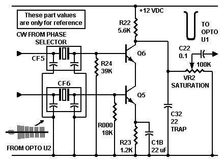
Alternate demodulator circuit with two series transistors. Ceramic 3.58 MHz filters replace LC filters.
Alternate demodulator circuit. Further thought about the Col-R-Tel demodulator brings me to an interesting alternate circuit. In this new circuit, the CW line (hue reference) has its own transistor. The two transistors together simulate the pentagrid tube in the tube Col-R-Tel. The new circuit is sort of an analog AND-gate. It will never pass just one of the two signals. To produce output, this demodulator requires both signals, and both must be in phase.
How it works. To pass and amplify a signal, the circuit's CW and chroma lines must both go high. Like two grid-leak detectors, the two base-emitter junctions clip off the negative excursions. As with conventional detectors, the circuit is insensitive to quadrature signals. The signals mix in the top transistor. Here, too, the CW gates the chroma. The collector circuit amplifies and inverts the detected and mixed signal. The bypassed bottom emitter allows for a fair amount of gain. Again, the detector with gain is a legacy of the tube Col-R-Tel. The gain is important because Col-R-Tel doesn't have a chroma amplifier. In this circuit, the detector gain replaces the loss of the chroma gain. Typical transistor detectors accept the CW signal at the emitter. Of course, in solid-state Col-R-Tel, this typical arrangement causes two disadvantages...
- We can't bypass the emitter: The gain suffers.
- We must invert the CW hue signal, because the emitter requires a low-going signal. Inversion requires changes to the Col-R-Tel phase splitter.
Better gating. The new circuit permits more certain gating, even when the chroma signal is very strong. With the previous circuit above, the chroma signal has to be much weaker than the CW hue reference. Otherwise, the circuit above might function as an analog OR-gate. Either the chroma or the CW hue reference could turn on the detector. Sometimes the signals would mix, and sometimes they wouldn't. Of course, the output filter would short out the reference signal. In that case, the output color difference signal would probably flicker on and off.
Ceramic filters. The new demodulator uses ceramic filters. One filter on each input replaces the typical, LC tuned circuit. The 3.58 MHz ceramic filters are small, inexpensive, and best of all, require no tuning. The filters' center pins couple transient suppression capacitors to ground. These capacitors are part of each filter IC. The filter inputs couple through RF capacitors that are off this drawing. Abracon, ECS, Murata and many other manufacturers make such filters.
Go to Page: 1 2 3 4 5 6 7 Next