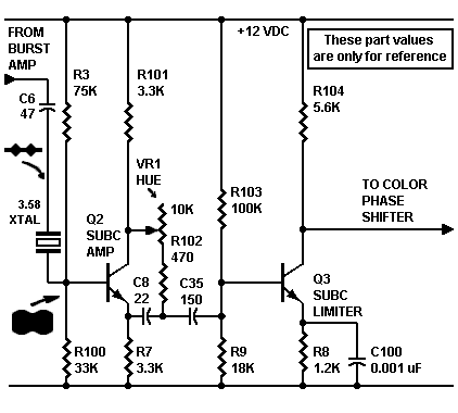
Hue potentiometer VR1 permits the viewer to adjust the subcarrier phase. This adjustment has the same effect as altering the chroma phase. The hue circuit replaces the "Color Lock" circuit in the original Col-R-Tel. Unlike the original circuit, our hue circuit doesn't require an expensive, front-panel adjustable inductor.
Hue control operation. Here's how the hue control works: Along with resistor R108 and capacitor C8, pot VR1 is an RC phase-shifter. These components select a variable mixture of the Q2 collector and emitter phase.
Phase splitter action. We mentioned that transistor Q2 outputs two phases. The transistor can do this because it's a phase splitter. The subcarrier signals at the Q2 collector and emitter are 180 degrees out of phase. Because of this phase difference, control VR1 can shift the color spectrum by up to 180 degrees. For example, VR1 could change the display color from green to magenta.
Subcarrier Limiter. Leaving Q2, the 3.58 MHz subcarrier enters the Q3 base. Transistor Q3 amplifies and limits the subcarrier signal. For some time after the color burst signal, the crystal continues to ring. Yet eventually, the mass of the crystal tends to damp out the oscillations. Col-R-Tel operation requires a reference subcarrier with a continuous waveform. Stabilizing the subcarrier is a job for the limiter. Throughout line-scanning time, the limiter maintains the crystal signal at a constant amplitude. This constant signal allows phasing transistor Q4 to derive three stable color reference signals.
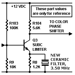
For consideration. Transistor Q3 isn't a traditional limiter. For the time being, I'm just using a Class-A stage here. I'm hoping that Q2 drives this stage hard enough that Q3 will clip on both peaks. If I don't see enough clipping, I might change the Q3 bias or replace Q3 with a Darlington. Also, the clipping will produce harmonics. I depend on the input tuned circuit at the demodulator to round off these harmonics. If I still find harmonics, I'll add a decoupling capacitor to Q3's collector.
|
Peaking crystal. In my experimental breadboard for this project, I included an important modification. I replaced the emitter bypass capacitor with a two-lead, ceramic resonator. We also call these devices filters. They function like crystals, but with a wider bandwidth and lower peak. I think that the device that I'm using is an Abricon® model. Of course, the resonator frequency is 3.58 MHz, the NTSC color reference frequency. At frequencies near 3.58 MHz, the resonator peaks the limiter gain. With enough of a peak, I won't need to switch to a Class-B limiter. The Class-B circuit would tend to clip one peak more than the other. I'd like to clip both peaks fairly equally. |

|
Go to Page: 1 2 3 4 5 6 7 Next
Before building anything, read our disclaimer!