Questions About Arduino Microcontroller Interfaces
QUESTION. I need to connect your preamp to an Arduino microcontroller. The Arduino input can't exceed five volts. I also want to isolate the Arduino from the outside world. How would I do this? (Question from Peter Laucks, 2010)
ANSWER. Consider an opto-isolator. You could buy a dedicated isolator. (Example: Vishay CNY75A or 83536 from Mouser.) But the easy way is to buy the infrared emitter and detector kit from Radio Shack.
The kit includes both an emitter and detector. The emitter is actually an LED that puts out invisible infrared light. The detector is an infrared phototransistor. (Kit contents actually vary. Some kits might substitute a photodiode for the phototransistor. The diode has faster response, but isn't as sensitive. For our purposes, either the diode or transistor should work.) The cost for the Radio Shack kit is only about $3.49.
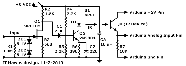
This DIY optocoupler can safely couple a guitar to the Arduino
The circuit that I suggest has three stages. The first stage Q1 is our JFET preamp. I've dropped off the output coupling capacitor and load resistor, because we don't need them this time. This stage provides a high impedance to the guitar and amplifies the signal just slightly. The second stage Q2 has its own coupling capacitor. This stage drives D1, the infrared LED with our guitar signal. A battery or small power supply operates these first two stages. The Arduino powers the third stage. Notice that the Arduino circuit has no electrical connection to the LED circuit or preamp. This lack of connection is what we mean by isolation. Our third stage Q3 is a phototransistor. For the sake of linearity and response speed, this stage is slightly degenerative. Q3 has a gain approaching 0.99. The LED stimulates the phototransistor to send the guitar audio to the Arduino microcontroller.
Your first test should be to confirm that the detector works. The book Getting Started with Arduino has the code and pictorial diagram. See pages 62 to 67. Never mind that the book uses a CdS sensor. (That would work, too, but CdS is laggy and wouldn’t reproduce music well.) You can test just the detector by aiming a TV remote control at it. Just click any button and look for a response. Make sure that you point the remote at the end or "head" of the detector.
Notice Different Power Voltages. In my circuit, I’m running the LED amp on nine volts, but the detector on five volts. That doesn’t matter, because the two amps don’t connect electrically.

|
Head-to-head only. The LED and phototransistor must face head-to-head. Bring the LED within an inch of the detector and the Arduino should indicate an AC input. To make the circuit more reliable, you could seal the detector and emitter in a short piece of heat shrink tubing. Again, the emitter D1 and detector Q3 must face one another in end-to-end fashion. The drawing at left shows what I mean. |
|
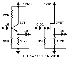
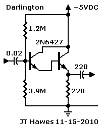
QUESTION. Please provide me with a circuit for a five-volt buffer. I need the buffer after a resistive ladder DAC. (Question from Peter Laucks, 2010) ANSWER. The buffer could be a tube, op amp, transistor, FET, or Darlington. Tubes are too big, too hot and too energy inefficient. Op amps add too much complexity for this project. That leaves transistors, JFETs and Darlingtons. You can power these solid-state devices from the Arduino. See the sample circuits nearby. The JFET design seems to be slightly better than the transistor design. (See the schematic at top-right.) The JFET's input impedance is very high and the output impedance is medium-low. A Darlington would perform even better, but the circuit would be slightly more complicated. (See the schematic at bottom-right.) Fortunately, the added complexity is inside the part! The reason for the Darlington’s superiority is that it can provide the lowest output impedance. I don’t know how low you need the output impedance to be. For the Darlington, I strongly recommend the 2N6426 from Mouser. Similar devices are the 2N6427 and MPSA13. Each Darlington “transistor” is actually an IC with two super beta transistors inside. Either one of these internal devices is a “superman.” Together, they rule the universe. If you don't want to try the 2N6426, you could build your own Darlington with two 2N3904 transistors from Radio Shack. Yet two 2N3904s only have a combined gain of 40K. The 2N6426 has a gain of 300K. Either version of the circuit should work, but the 2N6426 has the edge. (All that gain provides extra elbow room in the form of sensitivity. Actually, nobody uses the whole 300K. Think about it: In theory, 1 milliamp on the base gets you 300 amps on the collector. In real life, that much current would crater your PC board!) |
 |
QUESTION. Do you have an opto circuit to isolate an ULN2004 stepper drive chip from the Arduino? (Question from Peter Laucks, 2010)
ANSWER. Yes! I assume that you want the Arduino to power an opto that drives the motors through Darlington array ULN2004. See the schematic below.
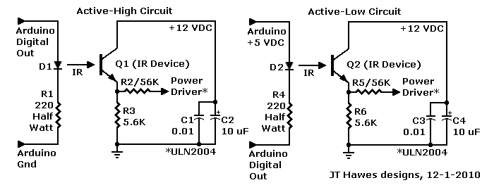
Here’s the circuit description: The Arduino digital output pulses an infrared LED that's in series with a 220-ohm, half-watt resistor. (One LED for each motor coil.) The resistor reduces the Arduino current to a safe value for the LED. Be sure to use a half-watt resistor here. The LED could be active-high or active-low. (The drawing below shows both versions of the circuit.)
|
The 12-volt stepper supply powers the phototransistor. The phototransistor’s emitter is in series with a 5.6K, quarter-watt resistor. Another resistor, 56K, quarter watt, couples the emitter signal to the Darlington array input. Whenever the LED lights, the phototransistor sends a high pulse to the motor drive chip. A 0.01 µF capacitor shunts digital noise to ground. A parallel 10 µF capacitor filters low-frequency ripple from the phototransistor supply. The 56K resistor is optional. The purpose of this resistor is to limit current and isolate the phototransistor from the Darlington array. Tweak the value of this resistor as necessary. If your driver requires a little extra voltage, you can remove the 56K resistor. Caution! Don't connect the Arduino ground to the 12-volt ground! |
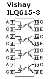 |
You might prefer to use an opto array instead of discrete optos. Then I suggest the Vishay 782-ILQ615-3 from Mouser. This part comes in a DIP-16 package and includes four opto-couplers. The LEDs in this package will operate adequately with only 10 mA.
Go to Page: 1 2 3 4 5 6 7 Next
|
♦ WARNING. This is your project. Your achievement is entirely yours. I assume no responsibility for your success in using methods on these pages. If you fail, the same is true. I neither make nor imply any warranty. I don't guarantee the accuracy or effectiveness of these methods. Parts, skill and assembly methods vary. So will your results. Proceed at your own risk. ♦ WARNING. Electronic projects can pose hazards. Soldering irons
can burn you. Chassis paint and solder are poisons. Even with battery projects,
wiring mistakes can start fires. If the schematic and description on this page
baffle you, this project is too advanced. Try something else. Again, damages,
injuries and errors are your responsibility. |
|
Copyright © 2010 by James T. Hawes. All rights reserved.
•URL: http://www.hawestv.com/mtv_FAQ/FAQ_fetpreamp6.htm
•Webmaster: James T. Hawes
|
JFET Preamp Pages
- Introduction
- Schematic & Parts
- How It Works
- Spec Spread
- Improve Performance
- MPF102 in Tillman Circuit
- Troubleshooting
- FAQ