FETs DeliverYou want that warm tube glow. You want that tube sustain. Plus you want portability and battery operation. It's a wonderful world. With a JFET, you can have all that and more. A JFET is the real deal. It delivers on the promise. And it's the only true answer. FETs Versus Op AmpsIf you've ever heard an op amp, you probably wonder why it sounds so pinched. The secret's in the circuit. A look inside reveals tens, hundreds or thousands of devices. You have feedback loops, compensation, current mirrors and a whole lot more. The op amp sounds different because it is different. Go with a FET: You're back to simple construction and sweet sound. The price can be less than an op amp costs. Space requirement. Besides, a FET takes up less space than an op amp does. All you need fits onto a little piece of perfboard. Average power drain is about 2 mA. A 9-volt battery lasts a long time. (Not as long as with the J201 circuit. But long enough.) FET Preamp Schematic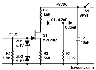
Figure 1. JFET preamp: Reduces attenuation of high frequencies by long cables. Voltage gain= 1.3. Sensitive: High impedance input. Low power and low noise. |
Parts List
| C1 | Capacitor, 4.7 μF, electrolytic |
| C2 | Capacitor, 10 μF, electrolytic |
| Q1 |
JFET, type MPF102, N-channel
|
| R1 | Resistor, 3.3M, 1/4-watt, 5%, metal film |
| R2 | Resistor, 1.5K, 1/4-watt, 5%, metal film |
| R3 | Resistor, 560Ω, 1/4-watt, 5%, metal film |
| R4 | Resistor, 220K, 1/4-watt, 5%, metal film |
| S1 | Switch, SPST, toggle |
| ZD1, ZD2 | Diode, 5.1 V, 1-watt zener (Requires 2) |
| NOTE: In some applications, the circuit works fine without R4, ZD1 and ZD2. | |
Trouble finding resistors?
Click... About Resistors.
Converting the Preamp to a Buffer•Circuit for loud players. Hearing too much distortion? Or just want to play loud? You might prefer a slightly different version of the preamp. In this version, the output comes off the source lead. Less of the signal appears across the source resistor than across the drain resistor. For this reason, this circuit is an attenuator. The reduced output signal is unlikely to overdrive your power amp. Here's the gain formula for this circuit... VG= ((2RS / RD) / 2) 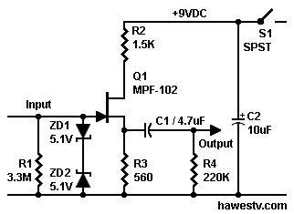
Figure 2. JFET attenuator: Just the ticket for loud players: Smooth tone. Non-inverting. Resists overdriving your power amp. •Standard buffer. The standard buffer is a source-follower that produces a non-inverted output at the source. The voltage gain is almost one (typically 0.95 with FETs). This circuit offers an advantage over the circuit in Figure 2. While the Figure 2 circuit likely won't overdrive your power amp, Figure 2 could overdrive itself. That is, this circuit attenuates its output, but not its input. The standard buffer is another matter. It attenuates its input. Especially on positive peaks, overdriving a standard buffer is difficult. 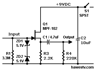
Figure 3. JFET standard buffer (source follower). Voltage gain: About 0.95. •Circuit for: Not enough output. If an attenuator doesn't offer enough output: Adjust the ratio of the drain and source resistors. For example: The sum of the two resistors is (1,500 + 560) ohms = 2,060 ohms. You can split this figure evenly, giving a 1K source resistor and a 1K drain resistor. The voltage gain is now one. Plus, the new circuit is a handy phase splitter: You can take the non-inverted signal from the JFET source. Or you can take the inverted signal from the drain. 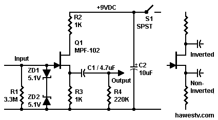
Figure 4. JFET preamp with voltage gain of 1. Phase splitter: Easy to choose inverting or non-inverting output. Clipping performance superior to operation with standard buffer. •Comparison to standard buffer. The Figure 4 circuit will compete very nicely with a standard buffer. An advantage of the phase splitter over the standard buffer: The output from the phase splitter is unlikely to clip on either the positive or negative excursion. Reason: The phase splitter operates with only half as much negative bias on the gate. Negative input problem. With the standard buffer (Figure 3), a negative input from the guitar might cause JFET channel closure. (Stomp box expert R.G. Keen mentions this situation.) Clipping of negative excursions is unlikely, but possible. In our phase splitter (Figure 4), the story is different: The bias voltage never approaches the cutoff, that is, the VGS(off) value. •Circuit for: Safe voltage Divider Bias. Other pages suggest a voltage divider to stably bias the JFET gate. Normally this voltage divider runs between the power rails. Unfortunately achieving halfway bias for the JFET entails matching the source resistor just right. The idea is that the proper source resistor keeps the gate at a safely negative potential. (Otherwise, inadvertent application of positive bias to the gate could destroy the JFET.) Worse still, resistor tolerances don't allow perfection. Avoid the risk and the bother! Try the circuit in Figure 5! Now you can safely achieve halfway bias. Here, the source resistor is your voltage divider. You can bias the JFET so that neither of your guitar's signal excursions will cause clipping. The Figure 5 circuit offers another advantage: It provides a higher input impedance (better sensitivity) than do typical voltage-divider bias circuits. The high impedance protects those crucial high notes from tone sucking. Superior tone is coming to an amplifier near you! 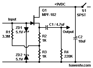
Figure 5. This JFET preamp also has a voltage gain of 1. This source-follower circuit adds feedback between the gate and source. The source resistor is a voltage divider that provides midway bias for the JFET. |
Go to Page: 1 2 3 4 5 6 7 FAQ Next