JFET Preamp Pages
- Introduction
- Schematic & Parts
- How It Works
- Spec Spread
- Improve Performance
- MPF102 in Tillman Circuit
- Troubleshooting
- FAQ
How to Tweak the Source Resistor
|
To Optimize Bias, Tweak Source Resistor Value |
Ideal Quiescent Drain Voltage for 9-volt JFET Circuit |
|||||||||||
| For Vs = | 1.0 | 1.1 | 1.2 | 1.3 | 1.4 | 1.5 | 1.6 | 1.7 | 1.8 | 1.9 | 2.0 |
| Ideal Vd = | 5.0 | 5.05 | 5.10 | 5.15 | 5.2 | 5.25 | 5.3 | 5.35 | 5.4 | 5.45 | 5.5 |
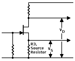
Headroom. What I mean by "ideal" is maximum headroom. This is the voltage that allows the most gain before clipping. For most devices in this circuit, the ideal drain voltage is 5 to 5.25 volts. (For some devices, this voltage might be lower or higher. See the table above.)
Best performance. In the discussion below, I'll assume that 5 volts is the ideal Vd voltage. If you want the best performance out of your amplifier, though, determine the ideal voltage for your own JFET. The formula is...
Formula for Ideal Drain VoltageIdeal Vd = [ ( ( 9 - Vs ) / 2 ) + Vs ] |
Run this formula, on the no-signal (quiescent) value of Vs. Remember, this is a static, DC voltage!
If you ever change JFETs in this circuit, repeat procedure below for the new device.
If Drain Voltage is Too High...
- Suppose that you see more than seven volts at the drain. You need to reduce the drain voltage (Vd). You must decrease the source resistor value. Buy two insulated clip leads and these resistors...
- Desolder and remove the source resistor from the circuit.
- In succession, clip in each resistor in the sequence. Don't let the source lead short to any other pin. After you make a connection, power up the circuit and retest the drain voltage.
- When the drain voltage is close to 5 volts, test the next resistor in the sequence.
- Recheck the source resistor voltage. It should now be lower.
- Rerun the Formula for Ideal Drain Voltage above.
- The new drain voltage isn't as good: Go back one value and solder that part into the source circuit. You're done with the optimization process.
- The new drain voltage is better: Repeat this step.
- None of the resistors provides a satisfactory Vd: The FET is faulty. Try a new one.
- Save the test resistors. If you ever replace the JFET, you'll need to tweak the bias on the replacement part.
| • 470Ω | • 390Ω | • 330 Ω | • 270Ω | • 220Ω |
| • 180Ω | • 150Ω | • 120Ω | • 100Ω | • 82Ω |
If Drain Voltage is Too Low...
- Suppose that you see less than 5 volts at the drain. You need to increase the drain voltage (Vd). You must increase the source resistor value. Buy two insulated clip leads and these resistors...
- Desolder and remove the source resistor from the circuit.
- In succession, clip in each resistor in the sequence. Don't let the source lead short to any other pin. After you make a connection, power up the circuit and retest the voltage.
- When the voltage is close to 5 volts, test the next resistor in the sequence.
- Recheck the source resistor voltage. It should now be higher.
- Rerun the Formula for Ideal Drain Voltage above.
- The new drain voltage isn't as good: Go back one value and solder that part into the source circuit. You're done with the optimization process.
- The new drain voltage is better: Repeat this step.
- None of the resistors provides a satisfactory Vd: The FET is faulty. Try a new one.
- Save the test resistors. If you ever replace the JFET, you'll need to tweak the bias on the replacement part.
| • 680Ω | • 750Ω | • 820Ω | • 1KΩ | • 1.2KΩ |
Resistor-Swap vs. Potentiometer Method. In case you wonder, the "resistor swap" is a better method than a potentiometer in the FET's source leg. With the resistor-swap method, you wind up with the exact, best standard resistor. With the potentiometer, you find a match, but then you must convert the match to a standard part. Also, you run the risk of measuring the pot the wrong way. Then you have a poorly biased FET. Add to these problems the fact that the potentiometer is a noise source. Plus, a knock or a bump can throw off your careful adjustment. A fixed part is much more dependable.
Don't be too picky. The method on this page helps you to cope with imperfect semiconductors. But don't expect this method to produce an exact result. Try to come within 10 or 15 percent of the ideal drain voltage. If you do, you'll have a winning circuit. It will serve you well. Perfection beyond this point is rare. If you land on the mark, consider yourself lucky. On the other hand, even our formula isn't flawless. It ignores the internal source resistance of the device. This internal resistance adds to Rs. For "extra credit," you can estimate your device's internal Rs. It's the reciprocal of your device's transconductance (Gm or Gfs). Transconductance varies by device, temperature, voltage, current and bias. For these reasons, internal Rs is beyond the scope of this page.
Go to Page: 1 2 4 5 6 7 FAQ Next
|
▲ WARNING. This is your project. Your achievement is entirely yours. I assume no responsibility for your success in using methods on these pages. If you fail, the same is true. I neither make nor imply any warranty. I don't guarantee the accuracy or effectiveness of these methods. Parts, skill and assembly methods vary. So will your results. Proceed at your own risk. ▲ WARNING. Electronic projects can pose hazards. Soldering irons can burn you. Chassis paint and solder are poisons. Even with battery projects, wiring mistakes can start fires. If the schematic and description on this page baffle you, this project is too advanced. Try something else. Again, damages, injuries and errors are your responsibility. — The Webmaster |
|
Copyright © 2007 by James T. Hawes. All rights reserved.
•URL: http://www.hawestv.com/fet_preamp/fetpreamp5.htm
|