Questions About Other Preamplifiers
|
QUESTION. JFETs are too fragile and fussy for me. Do you have a more durable circuit that will do the same thing? ANSWER. Yes! This circuit is one of the most famous in semiconductor history. I refer to the Darlington Pair, probably the most important and useful of all two-transistor circuits. In 1953, the Darlington invention brought Sidney Darlington world renown. Mr. Darlington was then a researcher at Bell Labs. He made his fabulous discovery during a weekend of tinkering with early, primitive transistors. On that weekend, he figured out an easy way to multiply the gain of a transistor. The gain increased not by a factor of one or ten. Instead, Darlington succeeded in squaring the gain! Today, many engineers and hobbyists know the Darlington, US patent 2,663,806, as a high-gain device. Some think that it's only for power amplifiers. Others think of a Darlington as a high-impedance amplifier. In fact, all of these notions are true. Darlington's brainstorm is an incredibly versatile amplifier. And it will work for us. You can apply the Darlington Pair's tremendous gain in an impedance converter amplifier. This circuit will have a tube-like high impedance input. |
|
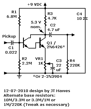
For pennies, you can buy a Darlington IC that looks exactly like a regular transistor. Buy a Fairchild type 2N6426 Darlington from Mouser. This remarkable device is the highest-gain Darlington that Mouser sells. Inside are two super-beta transistors. The total gain can be as high as 300,000! Other device types that will work well are the Fairchild type 2N6427 and the Freescale type MPSA13. All Electronics carries the MPSA13.
If you can't find a single-package Darlington, you can make one from two ordinary 2N3904 transistors. The result won't be as easy to wire. And it won't have nearly as much gain, but it will work.
Darlingtons are wild devices. The greatest challenge is just getting them to perform stably. Like lassoing a rocket, our circuit (above) stabilizes the Darlington for us. What we now have is exactly what we need: A very reliable amplifier with a high input impedance and a medium output impedance. The Darlington is as sturdy as any conventional transistor circuit. This device isn't as static-sensitive as are JFETs and MOSFETs. Build the circuit. See if you don't agree that Darlington invented an amazingly useful, versatile and great sounding transistor!
Construction Notes: As with other circuits on this site, tweaking of resistor values may be necessary. The emitter bypass capacitor C3 is optional. You can achieve variable gain and distortion with this circuit. When you use the emitter bypass capacitor, the gain varies with frequency. Below a pot value of about 100 ohms, the circuit attenuates low frequencies. You can improve low frequencies by increasing the capacitor size. If you don't need variable gain, replace VR1 with a 1K fixed resistor. The 220K load pulldown resistor and filter capacitor C4 are optional. Resistor R4 keeps the next stage from floating up. Capacitor C4 reduces power supply hum.
QUESTION. The Darlington output is very weak. Did I wire something wrong?
ANSWER. A common mistake is using two Darlington ICs. You should only use one Darlington. With two, the necessary base bias voltage doubles. Result: Your Darlington won’t turn on. The Darlington base must be 1.2 to 1.4 volts higher in voltage than the emitter. (This is the DC voltage without an input signal.)
Two Darlingtons would also produce excessive current gain. In fact, the gain would be 300K^2! (That’s a 9 with 10 zeroes after it.) For an input of one microamp, the circuit would attempt to output 10 kiloamps! If that were possible (it's not), your amp would burn clean through the floor. Fact: Each Darlington “transistor” is an IC with two super beta transistors inside. Either one of these internal devices is a “superman.” Together, they rule the universe.
How are you coupling the guitar's inductive pickup? Please couple the input coil through a capacitor. Without the capacitor, the pickup could load down the Darlington base.
Go to Page: 1 2 3 4 5 6 7 Back
|
♦ WARNING. This is your project. Your achievement is entirely yours. I assume no responsibility for your success in using methods on these pages. If you fail, the same is true. I neither make nor imply any warranty. I don't guarantee the accuracy or effectiveness of these methods. Parts, skill and assembly methods vary. So will your results. Proceed at your own risk. ♦ WARNING. Electronic projects can pose hazards. Soldering irons
can burn you. Chassis paint and solder are poisons. Even with battery projects,
wiring mistakes can start fires. If the schematic and description on this page
baffle you, this project is too advanced. Try something else. Again, damages,
injuries and errors are your responsibility. |
|
Copyright © 2011 by James T. Hawes. All rights reserved.
•URL: http://www.hawestv.com/mtv_FAQ/FAQ_fetpreamp6.htm
•Webmaster: James T. Hawes
|
JFET Preamp Pages
- Introduction
- Schematic & Parts
- How It Works
- Spec Spread
- Improve Performance
- MPF102 in Tillman Circuit
- Troubleshooting
- FAQ