Questions About Power Amplifiers
QUESTION. I'm building an amplified cigar-box guitar. The JFET preamp is a great start. But how can I boost the output enough to drive a speaker?
ANSWER. Today's semiconductors can do just what you need. For example, a Darlington or VMOS FET can drive a speaker directly. Just remember that the amplifier isn't a thing to itself. It needs power, usually a lot of it. In fact, the power supply could be the most difficult part of your project.
Fortunately for instant gratification, there's an easy way to get a speaker driver: Use a ready-made amplified speaker. These days, hamfests are brimming with surplus computer speakers. Add into the bargain that these speakers offer mid-to-high fidelity, and they're often stereo. You can add a pickup to your project and play in stereo! The speaker power supply usually comes with the speakers. When you buy, make sure that the speakers have volume controls. The controls are a tip-off that there's an amplifier inside.
You might not be lucky enough to get a power supply in the deal. In that case, saunter over to the next hamfest table. Don't worry. You'll find the supply. Just be sure to get one that's powerful enough. Typical computer speakers require 300 mA to about 2 amps. The input is DC voltage, and that varies, too. The most common voltages are 5, 6, 9 and 12 volts. The more powerful speakers take the higher voltages. A label on the bottom of the case usually provides ratings. This label usually only appears on one of the speakers, the heavier one. The heavier speaker contains the amplifier for both speakers.
QUESTION. I bought amplified speakers, but they didn't come with a power supply. How do I find the right power supply?
ANSWER. Here's what to look for in a supply...
- The current type. Make sure that you're buying a DC supply. Some supplies put out AC. Look at the plug diagram on the power supply label. This diagram specifies whether the inside or outside of the plug is positive. If you don't see a diagram, you might have an AC supply. This is fine if your speakers need AC. Yet most require DC. Baffled? Measure the supply output with a meter (DVM).
- Good wiring. The DVM test will also spot supplies with broken wires. The wires usually break near the plug or near the supply. If you suspect a break near the plug, you can replace the plug. Radio Shack and most hamfests will sell you a new plug. If you suspect a break near the supply, don't buy the supply. You can fix such a break, but you must disassemble the supply.
- The exact DC voltage rating that your amplifier requires. The amp and power supply must match.
- An output current rating that equals or exceeds what the amplifier requires. The closer, the better. Typical "wall wart" power supplies aren't regulated. The unloaded output voltage is higher than the rating. When you connect the supply, the amplifier draws down the voltage. If the supply puts out too much current, the amplifier might not draw the supply voltage down enough. Also, large supplies waste power. For these reasons, you can use a slightly larger supply. But avoid one that outputs three or four times the current that you need.
- An output plug polarity that matches the amplifier polarity. If necessary, you can cut off the plug and change the polarity.
- An output plug with the same length and diameter as the amplifier socket requires. Before buying the supply, try plugging the connector in. The plugs are color-coded. Notice the colored ring on the end of the power supply plug. If you know what color you need, matching is far easier. Some of the plugs are only slightly larger than others. If your only plug fits loosely, you'll need to change the plug.
QUESTION. Could I replace the preamplifier stages of my tube guitar amplifier with circuits like your JFET preamp?
ANSWER. Yes, you could! The circuit would work, too. Note that JFETs don't provide a "plug-in replacement." You must instead replace all the wiring for the entire tube stage. Whatever you do, please don't mangle a valuable antique!

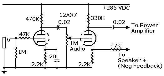
Input stages from Gibson GA-1RT guitar amplifier, a real classic
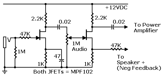
The circuit that I've described is a one-JFET design without much gain. You can significantly boost the gain by adding a source resistor bypass capacitor. The result would be something like one stage of the original tube preamp in a guitar amplifier. Next, you'd eliminate the 220K resistor on the output and couple in another stage.
You'd also have to invent a new power supply for your JFET preamplifier. Whatever you do, don't hitch up the tube power supply. It will spread JFET fragments all over the room. And probably all across the state. Instead, you need a good, ripple-free, low-voltage supply. Maybe you can use the filament supply with a doubler circuit and filter. Or in a pinch, you can even use a battery.

JFET redesign of Gibson input stages (Untested). Operates on 12 VDC power.
I'm not sure exactly how well the JFET version would work. JFETs can sound very fine, but I've never seen a tube-to-JFET sub book. What you propose to do is to replace one design with another. Nobody can say for sure if the new design is equivalent in every way. You'd have to try it, tweak it, and see how you like it. Fortunately, you can temporarily patch in a JFET amp. Remove the tubes. Disconnect the final coupling capacitor, isolating the old tube circuit. Set the JFET breadboard atop the tube chassis. (You can bolt your circuit down later.) Capacitively couple the JFET preamp to the tube power amp. A few alligator clips would do the job...
- One from the JFET drain capacitor to the power tube grid.
- One from the JFET ground to the tube amp ground.
Now connect your JFET preamp and test it out. If you don't like the sound, you can make a decision...
- Tweak the amp until it's perfect. For example, you might try different values for the 47μF feedback resistor.
- Disconnect the new preamp and return to that golden oldie tube sound. That is, go back to the original design.
You'll save power with the FETs. They behave a lot like tubes. And JFETs do sound nice.
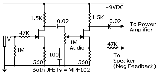
I mentioned battery operation. Some will want to operate the preamp on a nine-volt transistor battery. Nine-volt operation requires circuit changes. Here's a nine-volt version of my preamp...

JFET redesign of Gibson input stages (Untested). Operates on 9 VDC power.
QUESTION. Could I use another MPF102 stage as the power amp? (Question from Bill C. Harbour, 2010)
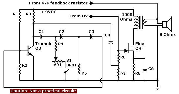
ANSWER. An MPF102 would work as the power amp. It really isn't an acceptable power device, though. Your speaker volume wouldn't be very loud. The output volume will be comparable to what you get from a transistor radio. (At best.) What you propose is somewhat like substituting a 12AU7 tube for a 6BQ5 power output tube. I doubt that anyone would do that. Yet maybe an earphone amp would use such a low-power design. The rest of this answer follows through on a hypothetical, low-power JFET circuit. The provided schematic isn't practical. It also depends on the preamplifier from an earlier question.
|
On the drawing's left side is Q3, a tremolo oscillator. On the right side is Q4, the JFET power amplifier. Half the tremolo signal mixes with the full input signal at gate resistors R7 and R8. ♦Caution. The Q3 tremolo oscillator (right) isn't a stomp box. Using this phase-shift oscillator in a stomp box requires designing a simple modulator circuit. If you can't do that, don't build this circuit. Also: The Q4 circuit isn't a practical amplifier. |

|
To increase speaker volume, increase the voltage or current at the speaker. This page tells how...
QUESTION. How do I get more power out of the amplifier? (Question from Bill C. Harbour, 2010)
ANSWER. Well, we're moving pretty far away from preamplifier topics. One way to boost output power is to increase the power (B+) voltage. Now we're not talking about a battery amplifier anymore. For example, you might use 30, 50 or even 100 volts. Of course, the MPF102 JFET tops out at 25 volts. You'll have to change devices. I don't recommend using it at over 20 volts.
Let's consider a two-FET rig. This time, our model is the venerable Fender Champ Model 5C1. We'll use high-voltage MOSFETs instead of JFETs. The preamplifier is an LND150 and the power amplifier is a DN2540. Supertex makes both parts. You can order them inexpensively from Mouser. I'm still thinking about this amplifier, so let's save the details for later.
The power limit for the LND150 is 500 volts. The limit for the DN2540 is 400 volts. Using them at a lesser voltage, such as 50 volts, is just fine. In fact, the curves indicate that a voltage of 100 or lower would be wise. Above 100 volts, the current-handling ability of these devices drops off.
If you plan to build such an amplifier, take care! The LND150 and DN2540 can handle swings up to 20 volts peak to peak. But no more. Also, MOSFETs sometimes oscillate at VHF frequencies. This oscillation can be destructive. Elsewhere on the Web, I see that people are supressing the oscillations by wiring a 1K resistor in the device gate. Another suppressor that I've used is a ferrite bead on the gate lead. Be careful not to let the leads short! Use the TO-220 package version of the DN2540 (DN2540N5-G). Bolt the device to a large, black, aluminum heat sink.
♦Warning. Beware of high voltages. These voltages could be lethal. Experimenting with circuits of this type can cause fires or part explosions. Operate all devices within their voltage, current and power specs. Use an appropriate wire gauge for the necessary power. If you don't understand these instructions, please don't build this project.
More when I get it...
QUESTION. Tubes and FETs are not interchangeable.
ANSWER. Right. Tubes and FETs are not interchangeable. Yet tube and FET circuits are often interchangeable. See books by Rufus Turner, Ken Cornell W2IMB and T.J. Lindsay. These technical writers point out how you can use JFETs in so-called “tube” circuits. I've proven this fact by building tube circuits with solid-state devices for 30 years. You must change resistor values, but the solid-state versions work.
My JFET preamplifier is an example of a “tube” circuit that translates into a JFET circuit. Many people have successfully built and used my preamp. I know because they write me. You appear to be one of the doubters. Why not take up a soldering iron and give the circuit a try?
Maybe you believe that when our society adopted solid-state, we abandoned tube circuits. This is a fallacy. In the 1950s through 1970s, engineers coined a special term for what I've done: Transistorize. You might look up this term on the Web. It means re-engineering tube circuits with solid-state devices. That method isn't only possible. It's the basis for many solid-state applications!
Go to Page: 1 2 3 4 5 6 7 Next
JFET Preamp Pages
- Introduction
- Schematic & Parts
- How It Works
- Spec Spread
- Improve Performance
- MPF102 in Tillman Circuit
- Troubleshooting
- FAQ