Contents
- FETs That Swing Like Tubes
- The LND150
- Schematic
- Parts
- LND150 Drain Curves
- The Un-Stomp Box
- Construction
- Experiments
- Why I Like the LND150
- Hear it!
- Trouble finding resistors?
- FAQ
|
FETs That Swing Like TubesYou want to overdrive that output section. Maybe it's a 6V6, 6L6 or even a 6BQ5. A JFET pedal sounds like a good idea, except for one problem: It doesn't put out a big voltage swing. And the swing is what your output section needs. You can jack up the preamp's power voltage to maybe 18 volts. But even an 18-volt supply doesn't provide enough of a swing. You need to hit that final stage hard. The question remains: How can you get the overdrive preamp to kick out the voltage you need? If only you could find a JFET that operates at tube power voltages! Now you can. But you'll have to give up on that JFET and switch to a depletion MOSFET. JFETs are wonderful devices. Yet finding one that operates at tube-type voltages just isn't easy. With depletion MOSFETs, the whole picture changes. Depletion MOSFETs that handle tube voltages are rare, but available. Mouser stocks the excellent Supertex® LND150N3-G, a device that takes care of business! Check Mouser or your favorite vendor and arrange to order half a dozen. You'll need a few for spares and experimenting. (In 2014, Microchip Technology Inc. acquired Supertex®. No worries. A Microchip® LND150 is equivalent to a Supertex® LND150: Truly “a rose by any other name.”) The LND150Depletion Mode. The LND150 differs from most MOSFETs that you'll find in stores. Like a JFET or a tube, this depletion MOSFET is a normally-on device. You can bias it just as you'd bias a tube. We'll operate the device in its saturation region. Here, the gain is better than what you'd expect from a 12AX7. And of course, the LND150 operates from a supply that would normally power tubes like the 12AX7. Linear. Don't let the LND150's pentode-like curves trouble you. Cathode or self-bias linearizes the FET's operation. You can improve the linearity even more by deleting the optional source bypass capacitor C2. The cost of operation without the capacitor is a decrease in gain. The LND150 has plenty of gain to spare. Also, despite the pentode curves, you don't need to wire up a screen and suppressor grid. And the FET requires no filament power source. You'll save gobs of power too, because there's no filament to use it. (You'd swear that the filament was there. This device is that good.) And don't forget: Surrounding components will run cool and last longer. In normal operation and with correct design, preamp FETs don't get very hot. Variable gain. The 3.3-megohm gate resistor R2 offers you several choices. You can substitute a potentiometer, allowing you to vary the stage sensitivity. The wiper of this potentiometer would connect to the LND150 gate. The pot value is also a matter of choice. Useful standard values are 500K, 1M, 5M and 10M. |
FET Preamp Schematic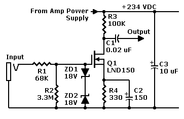
Parts List
LND150 Drain Curves
Above, the saturation region starts at the knees on the left. We're interested in curves for negative gate voltages (depletion mode). Note that this device also operates in enhancement mode (with positive bias)! |
If you use a fixed resistor, you may follow the schematic or select your own value. Smaller values make the stage less sensitive. Larger values make the stage more sensitive, but also more susceptible to noise pickup. The 3.3M resistor in the schematic seems to work well with most guitars and microphones.
The Un-Stompbox
Built-In Overdrive. An LND150 project isn't really a stompbox. That is, unless you can provide a portable, 200-volt power source. By the way, I don't recommend a series string of nine-volt batteries. Imagine the size! Imagine the replacement cost! Also please don't string 200-volt power lines across the stage. A DC-to-DC converter inside the effect could source the power. Yet a homemade preamp and converter might not be very small. What's the alternative? Add the LND150 overdrive as a new input channel on your guitar amp. Breadboard the circuit. It's tiny. Then patch the power leads into your amp's power supply. The output should drive your power tubes. (I can't say for sure. Circuits differ.)
Construction
Flexibility. The construction method for this preamp is quite flexible. You can use point-to-point wiring with terminal strips, perfboard, or a PC board. I recommend perfboard, such as Vectorbord®. Look for the type without copper traces. Use the general-purpose type with holes that are 0.042-inches in diameter. These holes should have 0.1-inch spacing.
Building the circuit.Unless you must fit the circuit into a cramped space, don't be stingy with the board. Be sure to allow for mounting space around the project. This circuit should then fit on a two-by-two or two-by-three inch board. Run bus wires across the top and bottom of the board's backside. Loop the ends of the wire through the last two holes in the board. The loops should poke out the top or component side of the board. While testing, you can connect these loops to your power source. Connect off-board jumpers to push-in stakes. (Vector® makes these stake terminals. I suggest part T42-1/C. Such hardware is available from Mouser.) Components mount on the top, with leads poking through the holes to the back of the board. Most of the wiring runs across the back of the board. Otherwise, build the circuit as nearly a literal copy of the schematic. That is, the power bus becomes the top of the board. Mount the FET halfway between the ground and power buses. Tack solder resistors between either power bus and the FET as appropriate. You can mount the board on standoff bushings. Most hardware stores stock such bushings.
Slip the tiny PC board into a quiet, cool corner of the amp cabinet. Mount the board on standoffs. Or screw it to a wall of the cabinet. Just keep the power lines short. Also, separate the input from your power transformer.
Experiments
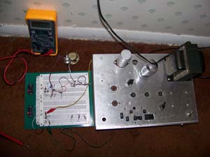 Above: My solid-state breadboard looks odd beside a tube power supply!
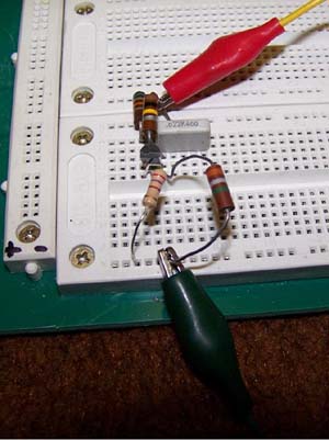 Above: Closeup of the LND150 circuit.
Gate resistors. Without substantially affecting performance, you can change the values of the gate resistors. For example, you can use a 75K or a 47K resistor at R1. For R2, values from 100K to 10M will work just fine. Remember that smaller values add a load to the input circuit (guitar). Larger values may let noise into your power amp. Also, larger values themselves might become a noticeable noise source. The gate is a good place to use low-noise resistors such as metal-film resistors.
Zener Diodes. The optional zener diodes protect the input from large signals that would damage the gate. If you're brave, you may leave off these diodes. The LND150 can't sustain transients of more than 20 volts peak-to-peak.
Why I like the LND150
|
The LND150 offers both similarities to, and advantages over tubes...
|

|
We get mail. If we can believe my correspondents, FET preamps sound very pleasing. We can expect the LND150 to share the mellow tone of the MPF102 FET.
Save Space. A depletion FET takes up less space than an tube does. All you need fits onto a little piece of perfboard. Average power drain is about 1.2 mA. You can "borrow" power for the circuit from your guitar amp power supply. Just make sure that you keep the power voltage down to 234 volts or so.
Try it. Duplicating tube amplifiers isn't my goal. Unique, attractive, seductive tone is my goal. Music engineers haven't yet invented all "beautiful tones." A FET preamp might well not sound "exactly like a tube," but what if the FET sounds really good? Then you'd try it, and so would others. Django Reinhardt, Charlie Christian, Robert Johnson, Les Paul, and Jimi Hendrix were each first with a trademark tone. They shook the earth. Thanks to them, it's still rocking. Have what it takes? Then what's keeping you from being the the next original? Lead the band. Rock the world. Try an LND150 booster today!
Hear it!
At last! The LND150 preamp achieves incomparable sound without parallel. Listen for yourself and believe. Visit Bill Harbour's page about the fabulous LND150 preamp!
- Click here for a genuine LND150 sound sample. In this sample, Bill demonstrates the substantial overdrive capabilities of this subminiature marvel.
- Bill describes how he uses the LND150 in two amplifiers with tube outputs. Click... Bill Harbour's Project Blog.
Trouble finding resistors?
Click... About Resistors.
Go to Page:
1
2
3
4
5
6
7
8
FAQ
Next
|
▲ WARNING. This is your project. Your achievement is entirely yours. I assume no responsibility for your success in using methods on these pages. If you fail, the same is true. I neither make nor imply any warranty. I don't guarantee the accuracy or effectiveness of these methods. Parts, skill and assembly methods vary. So will your results. Proceed at your own risk. ▲ WARNING. Electronic projects can pose hazards. Soldering irons can burn you. Chassis paint and solder are poisons. Even with battery projects, wiring mistakes can start fires. If the schematic and description on this page baffle you, this project is too advanced. Try something else. Again, damages, injuries and errors are your responsibility. — The Webmaster |
|
Copyright © 2010 by James T. Hawes. All rights reserved.
•URL:
http://www.hawestv.com/amp_projects/amp_solid_tube/fetpreamp_200v1.htm
|