
Tuned Circuit Alignment
Use a color bar generator. Make all measurements with an oscilloscope. The scope must have a flat response to 3.58 MHz.
|
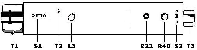
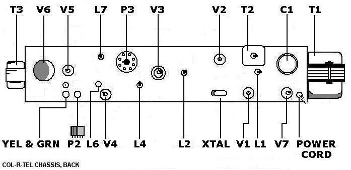
♦ NOTICE: The two pictorial diagrams on this page show locations of several parts in this procedure. • For transformer T2 & coil L3, see diagram above. • For coils L1, L2, L4, L7 & XTAL, see diagram at bottom of page. (Capacitors C2, C3 & C20 are inside the adapter box and don't appear in the diagrams.) |
- Following the installation instructions, connect the converter to a TV set.
- Connect the scope across resonant circuit L1 and C3. This tank circuit is in the grid of tube V1, a type 6U8. This is where you'll measure the chrominance signal.
- Set the scope timebase to 100 nanoseconds per division. With this setting, you can display a few cycles of the 3.58 MHz the chroma signal.
- Connect the color bar generator to the TV set.
- Watch the scope as you adjust TV set tuning and contrast controls.
- Continue adjusting until an approximately 1-volt peak-to-peak signal appears across the L1 / C3 tank.
|
|
|
- Connect the scope between one side of of the L2 phasing coil secondary and circuit ground.
- Adjust L1, T2, L2, L3, and L4 for maximum output with constant amplitude. On the scope, the waveform envelope must be flat. The envelope must have only a slight dip or peak at the horizontal pulse.
- Remove the color crystal from its socket. (See "XTAL" on the diagram below.)
- Move the scope probe to the output (green) lead.
- Adjust Capacitor C2 for maximum signal.
- Adjust Capacitor C20 or Coil L7 for minimum 3.58 MHz signal.
- Return the color crystal to its socket.
- Remove the test equipment.
- Return the Col-R-Tel unit to service.
Col-R-Tel chassis, back, top-left to right
Tube Reference
| Tube # | Type | Electrodes | Purpose |
| V1A | 6U8 | Triode | Burst Amp |
| V1B | 6U8 | Pentode | Crystal Ringer |
| V2A | 6U8 | Triode | Crystal Buffer |
| V2B | 6U8 | Pentode | Reference Limiter |
| V3 | 6BC7 | Diode (3) | Chroma Phase Selector |
| V4 | 6BE6 | Pentode | Chroma Detector |
| V5A | 12BH7 | Triode | Color Difference Amp |
| V5B | 12BH7 | Triode | Vertical Sync Preamp |
| V6 | 12BL7 | Triode (2) | Motor Driver |
| V7 | 6X7 | Diode (2) | Full-Wave Power Rectifier |
|
♦ NOTICE: COL-R-TEL TERMS & CONTROLS. COLOR LOCK is the same as the HUE or TINT control on other color TVs. COLOR GAIN is the same as the COLOR or SATURATION control on other color TVs. In most sets, the SATURATION control is part of the chroma bandpass amplifier circuit. Of course, the Col-R-Tel adapter has no such circuit. Col-R-Tel engineers moved the saturation control to the chroma detector circuit. Here, the control works superbly. |
Go to Page: 1 2 3 4 5 6 7 8 Next