All-in-one. In reverb history, 1966 was a big year. That was the year
that Gibbs released its mini-spring tank, only three inches long! Also,
Motorola and other manufacturers perfected the push-pull fader. This brilliant
invention allowed the driver to alter reverb intensity, speaker balance, and power
all from one control! Soon, Moto and other brands introduced the first reverbs
that fit under the dash: Springs and all!
All-in-one design comes to kits. Daniel Meyer (“Demco”)
and Popular Electronics Magazine responded with another innovation: They
brought out an all-in-one kit, the Mini-Verb in 1967. The circuit inside was
similar to that in the '66 kit. But now all the semiconductors were silicon, for
improved stability. The recovery amp was a Type-B design, for greater efficiency
than even the Motorola units offered. Best of all, everything fit under the dash!
Our installation instructions (for classic
cars only) appear below. Everything goes under the dash! The '67 kit
requires a rear speaker, which your car might already have.
✪ CAUTION. The reverb circuits on this page aren't guitar stomp boxes! Don't try
to adapt them for guitar. Guitar reverbs require a reverb tank driver on the input of the tank. (This tank
driver is an amplifier with a high impedance front end.)
✪ CAUTION: Instructions are Approximate. This page can't tell you exactly how to
connect the unit in a classic car. Each car manufacturer has its own wire colors and standards. By
studying drawings of reverb units, one can puzzle out the approximate instructions. Our educated
guesses appear below.
▲ WARNING. This page assumes the use of a classic radio receiver
(3 Wrms output, maximum) with the kit. Use the kit with
negative-ground vehicles only! The term “classic” refers to
a period radio and reverb from the 1960s. Never connect a classic reverb
unit to a contemporary radio. The two are incompatible. Connecting them will
likely cause a fire. Personal injury and equipment damage could result.
♦ NOTICE: Connection Numbering. In these instructions, wire connections appear as
numbers (“1”, “2”).
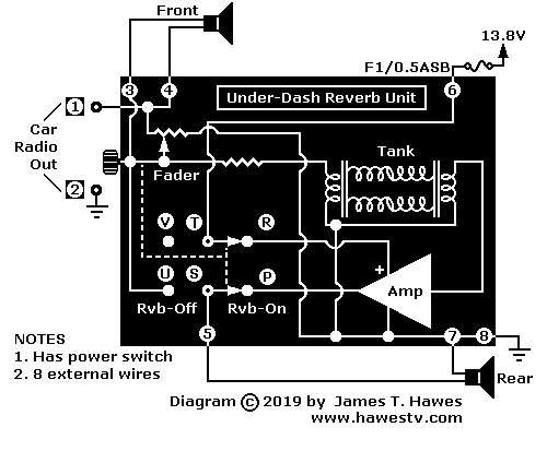
In-car wiring, 1967 reverb
✪ CAUTION: Speaker Dos and Don'ts (1967). Only use this kit with negative-ground
vehicles. The kit can operate 4, 8, or 10-ohm speakers.
Don't use this kit with 40-ohm or other types of speakers!
Don't use this kit with a speaker that carries a DC voltage on either of its leads.
Don't ground speakers to the car chassis.
Otherwise, kit malfunctions or equipment damage might result.
Rear Speaker Assembly
If necessary, mount the 6-by-9 rear-deck speaker and speaker grille. (Only 4, 8, or 10-ohm
speaker speakers are compatible with this unit!). Follow instructions that came with the
speaker and grille.
Under Dash Module
Turn off the ignition accessory switch, so that no power flows to the car radio.
At the car AM radio speaker, solder another wire to the “+” front speaker terminal.
(This is the terminal that carries the signal, and not the ground terminal.) The
new Wire 1 will carry the signal to the reverb unit.
Connect the free end of Wire 1 (“FRONT SPEAKER +”) to Reverb Terminal 4.
At the car AM radio speaker, disconnect Wire 2 (“FRONT SPEAKER -”). This wire
connects the speaker to the car ground terminal.
Connect the car radio output to ground (Wire 2).
Connect the “FRONT SPEAKER -” lead to Reverb Terminal 3.
Connect the “REAR SPEAKER +” lead to Reverb Terminal 5.
Connect Reverb Terminal 6 to +13.8V. (This voltage is available at
the accessories terminal of the car's ignition switch.)
Does the “REAR SPEAKER -” lead ground to the car chassis? YES: Disconnect
(or clip) the speaker ground wire. NO: Go to the next step.
Connect the “REAR SPEAKER -” lead to Reverb Terminal 7.
Ground Reverb Terminal 8 to the car ground system. The ground
connection must fasten to the car frame. (Example: An unpainted
screw.)
Optional Alignment
Turn on the car radio.
On the reverb, push in the rheostat knob.
On the reverb, turn the fader rheostat knob and listen.
Answer these questions...
Does turning the control vary the volume at the speakers?
Does the front volume increase to maximum at one extreme position?
Does the rear volume increase to maximum at the other extreme position?
Does the rear volume increase as the front volume decreases?
NO to any of these questions: Check and repair your work. YES to all
questions: Go to the next step.
On the reverb, pull out the fader rheostat knob.
Is the volume about the same as before, with the knob in? YES: Go to the next
step. NO: Service your work as necessary, until you can answer YES to this step.
Using the radio volume control, set the radio to your normal listening level.
Set the fader rheostat knob about halfway. Rear sound should probably be slightly
quieter than front sound (a matter of taste).
Level trimmer. Inside the reverb, trimmer resistor R4 (1K) adjusts preamp gain.
Adjust trimmer resistor R4 while listening to the rear speaker. Set R4 for your preferred level of
reverberation on the REAR speaker.
Turn the radio off. (Keep the reverb on.)
Output bias. With your DVM, measure the DC voltage between ground and the
junction of the two power transistors. (Measure Q6 collector to ground. The collector is the
transistor's top metal tab.) The target voltage is 6V. Popular Electronics says that
the target voltage is 6V. But: This voltage is half of your car battery voltage during a
typical drive. Depending on your power supply, this voltage could be somewhere between 6V
and 7V.
Voltage is below 6V: Use trimmer R8 (25K) to increase the voltage to 6V.
Voltage is above 6V: Use trimmer R8 to decrease the voltage to 6V. Voltage is
about 6V: Go to the next step.
Screw the top on the reverb unit.
Using sheet metal screws, mount the Under-Dash Module beneath the dashboard.
▲ WARNING. Anyone who builds these circuits does so at his own
risk. I take no responsibility for your success or failure. If you
injure yourself, damage your favorite oscilloscope or burn your house
down, you pay the damages.
If you aren't an advanced builder and experimenter,
don't even attempt this project.
From time to time, I will update and attempt to improve the information on
this page. I will make changes without notice.
I assume no responsibility for errors or inaccuracies that might occur on
these pages.
♦ NOTICE. If you'd like to contribute ideas or suggestions,
email me. Submitted ideas and suggestions become the property of
Hawes Amplifier Archive. I try to mention the source of
anything I use.
♦ NOTICE: FURTHER INFORMATION. The details that I have appear on these
pages. As I learn more, I'll add more data. Please don't email me for more
information.
♦ NOTICE.None of the reverb units on this page is for sale by me.
You might find one on eBay, though.
♦ NOTICE: Repairs, Modifications. Buy a Sams PhotoFact (schematic)
set on eBay. I don't have, nor do I provide schematics. I don't repair or modify
reverb units.