✪ CAUTION. The reverb circuits on this page aren't guitar stomp boxes! Don't try
to adapt them for guitar. Unlike car reverbs, a guitar reverb requires a tank driver at the tank input.
(This tank driver is an amplifier with a high impedance front end.)
A slab of perfboard, some bus wire, 60 parts, and “Bob's your
uncle!” Reverb time! Popular Electronics described a car reverb kit in February,
1966. Engineering wizard Daniel Meyer was the author of the groundbreaking reverb article.
Improved Mini-Kit. In May, 1967, Meyer offered a miniature version of his reverb
kit.
Meyer's 1966 reverb unit. Here, all-in-one model for use with
home stereo. The mobile model
had under-dash control & trunk-mount tank & amplifier.
(Kit, $15.00) Popular Electronics photo
The entire '67 kit fit under the dashboard. This kit even worked with stereo radios.
(Meyer was also the entrepreneur behind Demco and Southwest Technical Products.)
For tech insiders, Meyer provided schematics. A builder could forgo the kit
and build a car reverb from scratch.
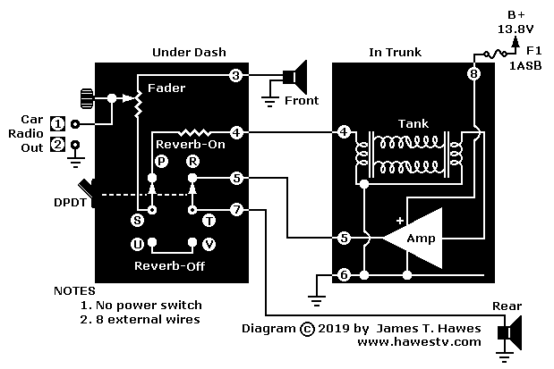
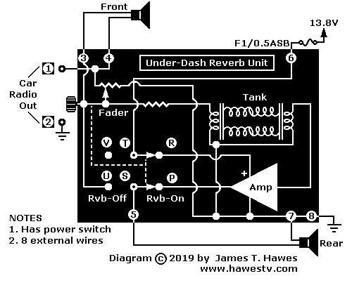
Meyer's diagrams helped builders to install the circuit in many
car types. The mobile circuit ran off 13.8-volt (“12V”) power from the car battery
(Negative ground). The input for the reverb springs was the car's AM radio.
Meyer's circuit recovered and amplified the output signal from the reverb springs. There
was a one-transistor preamp for gain. Then a pre-driver, and a complementary power amplifier. The
small, 3-watt power amplifier matched the maximum volume level from the AM radio. An under-dash
control unit included a fader that balanced the dry and wet signals. A switch toggled between
front and rear-normal vs. front-normal and rear-reverb sound. In the '67 kit, the fader
included the switch. The amplifier drove the rear speaker.
Take Liberties. Suppose that you want to build Meyer's Demco reverb unit. You'll have to
take liberties. Some “classic parts” aren't available anymore.
▲ WARNING. This page assumes the use of a classic radio receiver
(3 Wrms output, maximum) with the kit. Use the kit with
negative-ground vehicles only! The term “classic” refers to
a period radio and reverb from the 1960s. Never connect a classic reverb
unit to a contemporary radio. The two are incompatible. Connecting them will
likely cause a fire. Personal injury and equipment damage could result.
Reverb tank. To build these projects, you'll need a reverb tank (springs) that match what Meyer used...
Tank Specifications
Input Z
8-10Ω, grounded to chassis
Output Z
2KΩ-4KΩ, grounded to chassis
Delay Time
Medium, about 33 mS
Tank Length
1966 Kit: Short, 9.3"; 1967 Kit: 3"; Today: 5.3", available from Accutronics
Comment. Accutronics, Belton & Mod make such tanks. (Gibbs doesn't
manufacture tanks anymore.)
Left: Meyer's 1967 mini-reverb kit ($16.74). Tank & recovery amp fit
under dashboard. (Popular Electronics photo)
Convert to silicon. Replace germanium transistors with
silicon transistors. Silicon transistors (Si) are less leaky and more stable than
germanium (Ge) transistors. (Major chip foundries aren't making germanium devices
anymore.) Rebias the circuit to operate with silicon devices. Follow the table below.
Other considerations. When you switch from PNP to NPN, reverse polarized
devices in the circuit. (Polarized devices: Capacitors, diodes, transistors, batteries.)
▲ WARNING. Anyone who builds these circuits does so at his own
risk. I take no responsibility for your success or failure. If you
injure yourself, damage your favorite oscilloscope or burn your house
down, you pay the damages.
If you aren't an advanced builder and experimenter,
don't even attempt this project.
From time to time, I will update and attempt to improve the information on
this page. I will make changes without notice.
I assume no responsibility for errors or inaccuracies that might occur on
these pages.
✪ CAUTION. The 1966 project has no power on-off switch. The lacking
switch means that the reverb amplifier draws power from the car battery constantly. This is
true even when the reverb effect is inaudible. The amplifier will drain a small amount of
current from your battery. You can prevent this drain by adding a power switch to the
project. (Meyer's 1967 kit added a power-off feature.)
♦ NOTICE. If you'd like to contribute ideas or suggestions,
email me. Submitted ideas and suggestions become the property of
Hawes Amplifier Archive. I try to mention the source of
anything I use.
♦ NOTICE: FURTHER INFORMATION. The details that I have appear on these
pages. As I learn more, I'll add more data. Please don't email me for more
information.
♦ NOTICE.None of the reverb units on this page is for sale by me.
You might find one on eBay, though.
♦ NOTICE: Repairs, Modifications. Buy a Sams PhotoFact (schematic)
set on eBay. I don't have, nor do I provide schematics. I don't repair or modify
reverb units.