| Hawes Amplifier Archive |
|
| Car Reverbs | ||||||||||||||
|---|---|---|---|---|---|---|---|---|---|---|---|---|---|---|
|
|
How to Install Your Ford ReverbTwo. Maybe the Ford Studiosonic instructions below will help you to install other reverb brands, at least those by Motorola. This is a two-module reverb (pre-1966). It has an under-dash fader and a trunk-mounted tank and recovery amplifier. The installation requires a reverb speaker on the rear deck.
The car reverb circuit. Motorola built Studiosonic reverbs for Ford. Moto also build Vibrasonic for GM, plus several aftermarket brands. Typical circuits use two transistors as a preamp and power amp. Until about 1967, the transistors were usually PNP, germanium parts (often unavailable today). Autotransformers usually coupled transistor stages. The wiring was point-to-point. Later aftermarket brands contained three or four transistors. Meyer's famous Demco kits had six transistors and a PC board inside. The '67 kit used all silicon transistors. Ford/Motorola Studiosonic®
| |||||||||||||
|
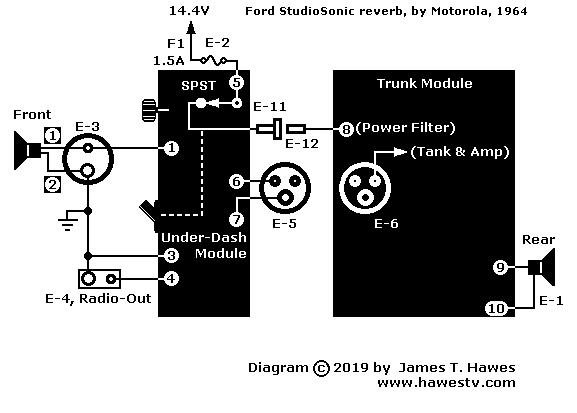
♦ NOTICE: Connection Numbering. In these instructions, wire connections appear as numbers (“1”, “2”). Ford also numbers its connectors. Each connector number begins with a letter “E” (E-1, E-2, E-3). Both numbering schemes appear in these instructions. |
|
|
|
In-car wiring, '64 Ford Studiosonic (2 module type) |
Under-Dash Module
- Turn off the ignition accessory switch, so that no power flows to the car radio.
- Connect B+ power lead "A" to the positive 14.4V accessory power source (+).
- Insert a 1.5A fuse into Fuse Receptacle E2.
- Disconnect the front speaker from the car AM radio (wires 1 and 2).
- Connect the front speaker to Receptacle E-3 (wires 1 and 2).
- Connect the car AM radio to reverb input Plug E-4 (wires 3 and 4). This connection provides the sound input and ground to the reverb tank.
- Mount the Under-Dash Module to the dashboard.
- Route the wiring harness from the Under-Dash Module to the Trunk Module. The harness has three wires, 6, 7, and 8. These wires terminate in Plug E-5 and Receptacle E11. Wires 6 and 7 (Plug E-5) carry the pre-reverb "dry" signal and signal ground. Wire 8 terminates in Receptacle E-11. This wire carries switched 14.4V power.
|
♦ NOTICE. Typically, Ford wiring to the rear speaker (and trunk module) runs through the passenger side of the car. If your car has a factory-installed rear speaker, no need for duplication: The wiring to the dashboard is already available. |
Trunk Module
- If necessary, mount the 6-by-9 rear-deck speaker and speaker grille (8-10 ohms). Follow instructions that came with the speaker and grille.
- Attach three-pin Plug E5 to Receptacle E-6 (wires 6 and 7) on the Trunk Module.
- Connect Receptacle E-11 (wire 8) from the Under-Dash Module and Plug E-12 on the Trunk Module.
- Connect the rear speaker to the Trunk Module at Receptacle E-1 (wires 9 and 10).
- Mount the Trunk Module inside the trunk. Hardware: Use mechanical dampers (rubber washers, springs, etc.) This hardware reduces spurious sounds when rough road pavement jostles the reverb springs.
Go to Page: 1 2 3 4 5 6 7 8 9 10 11 12 13 Next
|
▲ WARNING. Anyone who builds these circuits does so at his own risk. I take no responsibility for your success or failure. If you injure yourself, damage your favorite oscilloscope or burn your house down, you pay the damages. If you aren't an advanced builder and experimenter, don't even attempt this project. From time to time, I will update and attempt to improve the information on this page. I will make changes without notice. I assume no responsibility for errors or inaccuracies that might occur on these pages. |
|
♦ NOTICE. If you'd like to contribute ideas or suggestions, email me. Submitted ideas and suggestions become the property of Hawes Amplifier Archive. I try to mention the source of anything I use. |
|
♦ NOTICE: FURTHER INFORMATION. The details that I have appear on these pages. As I learn more, I'll add more data. Please don't email me for more information. |
|
♦ NOTICE. None of the reverb units on this page is for sale by me. You might find one on eBay, though.
|
|
♦ NOTICE: Repairs, Modifications. Buy a Sams PhotoFact (schematic) set on eBay. I don't have, nor do I provide schematics. I don't repair or modify reverb units.
|
|
Copyright © 2019 by James T. Hawes. All rights reserved.
•URL: http://www.hawestv.com/amp_projects/reverb/reverb_car06.htm
|
Contents
