|
• NOTICE. On this page, we're talking about JFETs and depletion MOSFETs. Not enhancement MOSFETs. Not any other variety of FET. (FETs are a large family, and not all “cousins” behave the same way.) |
What Went BeforeThe previous page introduces Pentode Mode and Triode Mode for JFETs and depletion MOSFETs. That page also describes how to find plate resistance and amplification factor for these solid-state devices. This page continues the discussion, including schematics for practical circuits. |

|
Triode Mode
|
In Triode Mode, a FET behaves in a linear fashion. That is, as drain voltage RD increases, so does drain current ID. Result: The delightful, euphonious tone that only a triode can produce. This linear behavior lasts until the device reaches its pinch-off voltage. To the right of pinch-off is a “knee” in the drain curve graph. At the knee, the FET channel saturates. Then the maximum safe current flows. During saturation, drain current ceases to effect drain voltage. The device becomes a voltage-controlled current source. |
Fig. 1. Triode Mode, left side of the graph (red outline). (1.) The green line marks the edge of the usable section. |
|
Triode Region Shape. See Figure 1. Note that pinch-off and the knee occur at a different point in each curve. As gate voltage VGS becomes more negative, the Triode Region narrows. The region as a whole is roughly the shape of a right triangle: The apex is at the bottom-left, and the hypotenuse on the right. The real estate at the top-left section is outside the curves and unusable. My experiments show that the bottom few curves are also unusable. Pentode Mode: A Review. As the previous page said: In the Constant-Current Region, a FET acts like a pentode. This fact is the source of the terms “Pentode Region” and “Pentode Mode.” Pentode-Mode behavior occurs in the Pentode Region, on the right side of the drain curves. Similarly, Triode Mode occurs in the Triode Region, on the left side of the drain curves. The drain voltage selects the region of operation. In both regions, the gate bias selects the drain current, ID. Uniquely in the Triode Region, the drain voltage also affects drain current. Engineers design most amplifier circuits to operate in the Pentode Mode. Perhaps this fact is why the Triode Region is vestigial. As we'll see, the Triode Region is most useful anyway. |
|
Uses for the FET Triode Mode
|
Engineers use the Triode Mode (TM) to implement voltage-controlled resistors. But there's a catch: Most FETs only operate in Triode Mode within the first few volts of drain potential. That is, when the drain voltage is left of the pinch-off potential. Broad Triode Mode. On the other hand, some FETs have a high pinch-off voltage. (Examples: Up to 10 volts for the •2N4304 by InterFET. A lovely, 8-volt maximum for the •2N3819 and the •MPF102.) With a high pinch-off voltage, the triode region is fairly broad. A circuit designer might reckon that this broad region is a frontier to develop. |
Fig. 2. Voltage-controlled resistor application (2.) |
|
Figure 3 expands an example of the Triode Mode so that we can study it carefully. These curves reveal triode-like behavior: Drain voltage affects drain current. This situation is most unlike the behavior within the Pentode Mode (Constant-Current Mode). There, drain voltage has little effect on drain current. |
Fig. 3. Triode Mode for 2N5484, expanded curves (3.) |
A Novel, Triode-Mode Preamp
|
Could a Triode-Mode audio amp be possible? I wondered. I couldn't find any useful applications online. But might such applications be achievable? Maybe so! My TM circuit is a conventional, Class-A amplifier that operates in a unusual region: Triode Mode. (See Figure 3.) My approach avoids gimmickry: No “magic components.” I abstained from bludgeoning a JFET into an improvised device with tube-like manners. |

|
|
First one? Could this preamp be the first of its kind? Possibly, at least with the device that I used. Better yet, my TM preamp seems to work well, and doesn't cost much to try. |
|
|
Design process. I started with my Pentode Mode FET preamp circuit. That circuit uses an MPF102 JFET. A 2N3819 is similar, and what I chose for this project. According to device curves, the Triode-Mode operation region for either device is broad, a requirement. (See Fig. 8). Here in three steps is how I proceeded... 1. Move VD left. The drain voltage controls the left-right, or X-axis. By reducing VD, I moved the drain voltage leftward, from 9 to 3 VDC. Now, my device would operate smack in the middle of the Triode Mode. 2. Move ID up. The first test circuit didn't work. I needed to increase the drain current. On the Y-axis, I moved the operating point upward. I did that by reducing RS and RD. |
Fig. 4. Above is the method that I used to move the operation zone into the Triode Mode. (4.) 
Fig. 5. Triode-mode preamp. Would like to hear a guitar through it! |
|
3. Tweak RS. A further RS reduction shifted the drain voltage to exactly where it should be, 1.5 volts. I assembled the Triode-Mode circuit on August 28, 2020. My new design biases properly: VD (average) measures 1.5 volts, about ideal. See Figure 5. (The test circuit omitted coupling capacitors and protection devices, such as gate zeners.) |
Fig. 6. Perfboard layout |
|
Success. There were two successful
builds, one on a solderless breadboard, and one
on a perfboard. In the final circuit, two
separate devices each produced 1.5 volts at the
drain. The average current draw was five
milliamps. Let's locate the operation zone
using Figure 8: The Triode-Mode circuit
operates on the “-0.2V” curve.
(RS provides source bias of
[47Ω x 0.0047A]= 0.22V |
Fig. 7. Circuit under power, with VD reading 1.42VDC, 95% of goal. |
| Triode-Mode Preamp (3 Volts) | |||||||
| Design Date | JFET Type | RG | RD | RS | ID | VDQ (Avg) | VGAIN |
| 8-28-2020 | 2N3819 | 1M | 270Ω | 47Ω | 4.7 mA | 1.5VDC | 2.9 |
| 9-7-2020 | Changed RG to 3.3M. | ||||||
|
♦ CAUTION: Top Drain Curve. The highest drain curve in Figures 1, 4, and 8 tops out at just under 7 mA. The flat part of this curve is at IDSS, or 0V bias. Yet the manufacturer's spec for IDSS covers a range between 2 mA and 20 mA. That is, the top curve could be higher or lower than where it appears on Figure 1. On this figure, my Triode-Mode circuits should operate within the Triode Region. Still, due to spec variations, not all devices would operate in the Triode Region. |
Current Draw
|
School of Hard Knocks. Experiments also included the attempt to design a more current-stingy amp. This amp would have had a two-milliamp average draw. Yet the attempt failed. The 2N3819 remained off. Reducing the source resistor value to zero ohms delivered no change. (At that point, I had a three milliamp, nonfunctional circuit.) The drain remained at VDD (the supply potential), indicating ID pinch-off. The lack of drain voltage change suggested the need to increase ID. |
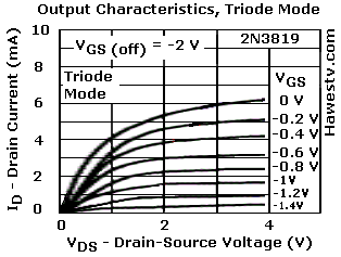 Fig. 8. Expanded Triode Mode for 2N3819. (Actually extends
to 8 V. I trimmed it off where the curves are still partly diagonal.)
(5.)
Fig. 8. Expanded Triode Mode for 2N3819. (Actually extends
to 8 V. I trimmed it off where the curves are still partly diagonal.)
(5.)
|
|
A few more milliamps of current moved the operation zone onto a more diagonal curve, promising enhanced linearity. The higher curves also enjoy a wider Triode Region than the lower curves offer. |
|
|
♦ CAUTION: FIGURE 8. I stretched this figure graphically, not mathematically. As a result, the slope of the curves is steeper than it appears. The stretching process adds other inaccuracies. For instance, the horizontal span between data points is wider than in the vertical dimension. |
Power Source

|
Penlight power. The new circuit only draws 7.5 mW. That's 15 mW less than my Pentode-Mode JFET preamp requires. Two penlight cells should keep me in Triode Mode for a long time. I'll use two cells in series, either AA or AAA. |
For BuildersMods. You may change resistor RG to any value from 100K to 10M. For larger values, I suggest using metal-film resistors for their low-noise characteristic. To dial in the proper, 1.5V bias VD, adjustment of RS might be necessary. Otherwise, I don't recommend altering the RD and RS values. You may use a gate-stop resistor if you wish. I suggest 68KΩ. For Musicians: If you plan to play loud, a 1M (or larger) gate-stop resistor might be necessary, or the preamp might clip. Capacitor values are suggestions. Substitute FETs: See Other Triode-Mode Devices, toward the bottom of this page. |
|
|
Stages. This preamplifier is suitable for use in guitar amps. You may cascade two or more such preamplifiers. Inputs. For use with piezo pickups, the input capacitor is optional. Some amps use input caps. They isolate the amp from DC in effects circuits that could upset the bias on the FET input. Other amps don't have the capacitor. Your choice. If you go without the capacitor, please use a 68K grid-stop resistor. |
|
Outputs. Low-impedance headphones (32Ω) will load the preamp
down, as will typical PM speakers. For use with medium-impedance outputs, use
a larger-value output capacitor, at least 4.7 µF. For use with
high-impedance pickups or cascade amps, the schematic capacitor value will
be fine. I suggest polypropylene capacitors.
For more gain, you may add a source-resistor bypass capacitor. See the two-stage cascade amplifier below. I haven't built this version, but it will probably work. Since the source resistor is small though, the bypass capacitor must be large. This capacitor should be an aluminum electrolytic type. Use the best quality cap that you can afford. If the amp howls, you'll have to do without the bypass cap. You know the maxim: “Gain is great. Instability ain't.” |
|
|
Fig. 9. Cascaded, two-stage version of my Triode-Mode amp. Includes grid-stop resistors at the front end. For guitar or mike. With a third stage, might drive a power MOSFET output. Experimental! I haven't built it. |
|
|
What type power amp (PA)? If you need a power amp to drive a speaker, you may add the PA after the second JFET stage. The three-volt power supply will be insufficient for the power amplifier. To produce a reasonable volume at the speaker, drive the MOSFET with 30, 50, or more volts. Pick a MOSFET that can produce about 60 mA at the chosen power voltage. Then you can use a tube output transformer with your PA. Antique Electronic Supply sells such transformers (Hammond, and other brands). Another vendor who can help you is Triode Electronics. |
|
Fig. 10. Block diagram: Triode-Mode amp with level shifter |
|
Level-shifter. Using the Triode-Mode preamp with a MOSFET output might require a level-shifter stage. This stage would stand between the preamp and the power amp. A JFET or BJT transistor operating at the power amp's drain voltage would be appropriate. The level shifter would increase the preamp output voltage to the threshold voltage of the MOSFET. Otherwise, a MOSFET power amplifier with a low threshold voltage might be necessary. |
1.5-Volt Preamp
|
How low can you go? How about a 1.5V preamp? On September 30, 2020, I built a 1.5-volt Triode-Mode preamp. This experiment produced a working amplifier with a measured output voltage of 0.76V. The schematic appears at right. Think of operating on just one penlight cell! Below are some other specs for the preamp... |
Fig. 11. 1.5-volt, Triode-Mode amplifier experiment |
| Triode-Mode Preamp (1.5 Volts) | |||||||
| Design Date | JFET Type | RG | RD | RS | ID | VDQ (Avg) | VGAIN |
| 9-30-2020 | 2N3819 | 1M | 180 | 15 | 3.8 mA | 0.76VDC | 6 |
Other Triode-Mode Devices
|
Legacy device. Triode-Mode devices require a high pinch-off voltage, so that the Triode Region is broad. FETs with these desirable characteristics tend to be legacy devices. Fortunately, there are foundries that still make these devices. More about that topic in a moment. First, we should focus on concerns about device replacement in our Triode-Mode circuits. The CAUTION below discusses those concerns. |
|
♦ CAUTION: DEVICE TYPE. In the circuits on this page, very few devices can substitute for the 2N3819 or MPF102.
|
|
To find a substitute FET, you may consult InterFET, a foundry in Texas. (6.) InterFET claims to be the world's largest source of JFETs. Its stock is impressive. But certainly it isn't the only source. Mouser Electronics (7.) stocks FETs by and many foundries. The names of some of these foundries appear in the table below.
(To contact companies in the foundry table, please click the footnotes.) FETs from these sources might help with the projects on this page, or with similar projects. Mouser's competitive pricing among different brands is an important advantage over buying factory-direct. I culled the part numbers below from part specs for 500 devices. Each part on my list has a pinch-off voltage of 7.8 to 10 volts. For my research, I used InterFET's JFET Master Table, and manufacturer datasheets. The InterFET table is an excellent reference. (14.) |
|||||||||
JFETs with High Pinch-Off Voltages(May be compatible with the project on this page) |
|||
| •2N3823 | •2N4304 | •2N6449 | •2N6450 |
| •BF245A | •BF256B | •IFN6449 | •IFN6450 |
| •J203 | •PN3458 | ||
| NOTE: I haven't tested these parts. I offer no guarantee of compatibility in the circuit on this page. | |||
Go to Page: 1 2 3 4 5 6 Back
|
▲ WARNING. This is your project. Your achievement is entirely yours. I assume no responsibility for your success in using methods on these pages. If you fail, the same is true. I neither make nor imply any warranty. I don't guarantee the accuracy or effectiveness of these methods. Parts, skill and assembly methods vary. So will your results. Proceed at your own risk. ▲ WARNING. Electronic projects can pose hazards. Soldering irons can burn you. Chassis paint and solder are poisons. Even with battery projects, wiring mistakes can start fires. If this page baffles you, this project is too advanced. Try something else. Again, damages, injuries and errors are your responsibility. — The Webmaster |
|
♦ CAUTION: SPEC SPREAD. Between devices, JFET and depletion MOS specs vary considerably. New builds of the Triode-Mode circuits in this article might not produce the same output voltages. Also: Whether these Triode-Mode amps are linear across the audio band is an unknown. |
Contents
- What Went Before
- Triode Mode
- Uses for the FET Triode Mode
- A Novel, Triode-Mode Preamp
- Footnotes
- Current Draw
- Power Source
- For Builders
- 1.5-Volt Preamp
- Other Triode-Mode Devices
- Table, FETs with High Pinch-Off Voltages
Figures
- Fig. 1. Graph: Triode Mode
- Fig. 2. Schematic: Voltage-Controlled Resistor
- Fig. 3. Graph: Triode-Mode Expanded Curves, 2N5484
- Fig. 4. Graph: Method, Moving to Triode Mode
- Fig. 5. Schematic: Original Triode-Mode Preamp
- Fig. 6. Perfboard Layout
- Fig. 7. Circuit Under Power, With VD Reading 1.42VDC, 95% of Goal
- Fig. 8. Graph: Expanded Triode Mode for 2N3819
- Fig. 9. Schematic: 2-Stage, Triode-Mode Preamp
- Fig. 10. Diagram: Level-Shifter
- Fig. 11. Schematic: 1.5-Volt, Triode-Mode Preamp