| ▲ EPILEPSY WARNING. For some people, blinking or moving patterns may cause seizures or loss of consciousness. This page contains two animations with such patterns. Are you sensitive to moving patterns? Have you experienced epilepsy symptoms? If “YES” to either question: Please consult your doctor before viewing this page. |
| • NOTICE. For more information on a topic, you may click the related footnote number. (Example: [Ben., 47]) |
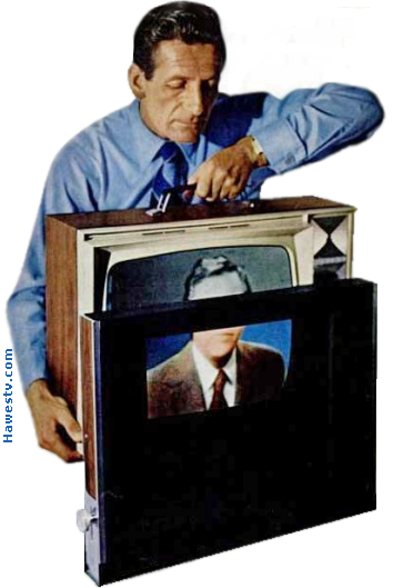
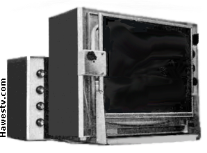
Ronald M. Benrey holding black-and-white, 20" TV behind Spectrac prototype. Spectrac colors video image behind scanning belt. (Popular Science) [Ben., front cov., 45] |
Spectrac: Color for a
|
|
|
|
Belt & Filters
|
Belt. The Spectrac TV viewer watched the monochrome picture through a moving belt. The belt traveled horizontally across the TV screen. Running across the belt in a gentle slant to the vertical were opaque black stripes: Hundreds of stripes. From the viewer's perspective, the front of the belt moved from right to left. The back of the belt moved from left to right. (The viewer looked through both front and back.) Invisible. At a normal viewing distance, the stripes were invisible. Each stripe was only 0.022 inch wide. Between stripes, the belt was clear. [Ben., 46], [Top., 7, Col. 3] Color filter. Between layers of the belt was a stationary filter. The filter bore stationary, slanted, color stripes. The colors were transparent. Each stripe was 0.022 inch wide, matching the width of each disc stripe. The reason for the size match was this: Belt movement exposed a red stripe or a cyan stripe. The monochrome picture played behind these stripe filters. [Ben., 46] (Incidentally, cyan is a mixture of the primary colors blue and green.) |
|
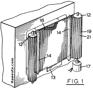
Drawing of Spectrac belt from U.S. patent. Highlights: 12—Spaced rollers for belt drive; 14—Idler rollers; 16—2-Color stripe filter; 17—Roller drive motor; 19—Opaque stripe; 21—Transparent stripe. [Top., 1, Fig. 1; 7, Col. 4] |
Stripes on the belt. Stripes on the front of the belt slanted left, in parallel with the color stripes. [Top., 7, Col. 4] On the back of the belt, the stripes slanted right. From the viewing position, the belt moved from right to left. [Ben., 46] Color diamonds. Result: The belt alternately exposed or obscured portions of color stripes. Each exposed portion was the shape of a tiny diamond. The diamonds were either red or cyan. [Ben., 45] Red or Cyan Screen. Due to belt travel, “diamonds” swept down the screen. After the screen became entirely red, cyan would begin to paint over the screen. Soon the screen would be entirely cyan. And then red would creep over the cyan again. [Ben., 46-47] |
|
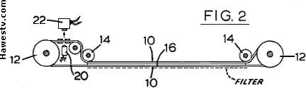
Top view, Belt from patent. 10—Belt; 20—Photocell pickup; 22—Exciter lamp. (Other callouts same as on Fig. 1, above.) [Top., 1, Fig. 2; 7, Col. 4; 8, Col, 6] |
Spectrac Advantages
|
|||||||||
Source: Author
|
|
||||||||
|
|||||||||
Spectrac Disadvantages
|
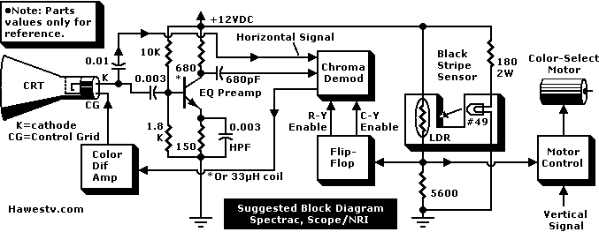
Neither Benrey nor Spectrac patent went into detail about electronics. Basis for diagram above is Col-R-Tel, & television & control theory. (Circuits aren't practical.) Diagram covers either Spectrac, or 1965 converter by Scope. (Source: Author) [Lac., 33], [Luc., 138], [Ha.1], [Ha.2, 3-5] |
What Became of Spectrac?
|
Demise of Spectrac. After CES 1971, the progress on the Spectrac project depended on the availability of venture capital: Specifically, a Canadian government loan. The loan was necessary so that Spectrac Ltd. could finish research and start mass production and marketing. But the government denied the loan and a subsequent appeal. Without funds, Spectrac's parent company Topping Electronics returned to its R&D business. [Kar., 2]
|
|
Still in business. Topping Electronics still maintains offices in Scarborough, Ontario. The company makes traffic control equipment. [T.E. pg.] Frederick V. Topping retired from his Topping Electronics in 1989. Afterward, Topping Electronics became a division of InspecTech Analygas Group Inc. Topping died in September, 1999. [Ill.] |

Source: Author
|
| Above: How Spectrac colors screen (simulation; exaggerated stripe size) | |
Scope TV Color ConverterRival product. How much competition did Spectrac face? The closest product to a “Spectrac competitor” was the 1965 Scope converter. (Apparently, neither Scope nor Spectrac went into broad distribution. They may have been competitive ideas, but they weren't marketing opponents.) Scope's Two-color filter. Like Spectrac, Scope suspended a two-color stripe filter over the TV screen. In Scope's rendition, the stripes were orange and teal. (Teal is slightly bluer than cyan.) Instead of a traveling belt to block one or the other color, Scope employed a moving screen overlay. [Lac., 33] |
|
|||||||||||
Scope color converter & adapter. Photo required extensive retouching by author. [Lac., 33] |
The Scope overlay bore vertical, opaque black stripes. The black stripes alternated with transparent stripes. A linear vibrator positioned the black stripes to obscure either the orange or the teal filter stripes: Very similar to Spectrac, except that Scope's linear vibrator pulsed rapidly. (But Scope's overlay didn't move far: In both ways, unlike the leisurely progression and long travel of the Spectrac stripe belt.) [Lac., 33] The TV vertical signal fed through a power amplifier that drove the vibrator. The drive electronics must have been close to what Spectrac used. [Lac., 33] |
|
NRI Connection. In 1965, NRI Schools was producing the Scope converter. NRI announced that it planned to market the Scope system to TV manufacturers. The goal was a $200, two-color TV. The Scope converter unit by itself would market for $109. [Lac., 33] |

Source: Author
|
| Right, above: Scope simulation, painting screen with color. (Exaggerated stripe size.) | |
About Scope & NRI. Scope was a Falls Church, Virginia concern. NRI was a technical correspondence school in Washington, D.C. [Lac., 33], [NRI, 29-30]
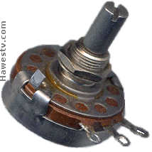
Potentiometer (Allen Bradley)
|
|
||||
Bibliography
|
https://www.earlytelevision.org/pdf/pop_sci_12-71.pdf (Access on February 1, 2022.) •Re: Many engineers produced versions of color television with only two, instead of three primary colors. One of these versions was Spectrac: Sensation at Summer Consumer Electronics Show in 1971. (Access on January 19, 2022.) •Re: Color shifts that one can expect when color gamut is line that runs between two primaries on color wheel. In case of Spectrac, these colors are red & cyan. https://www.earlytelevision.org/pdf/colortel_manual.pdf (Access on January 30, 2022.) •Re: Manual for Col-R-Tel, 1955 predecessor of Spectrac & Scope. Col-R-Tel could reproduce 3 primary colors. Six connections to television set would have been similar or same. Exception: Col-R-Tel had “size” box that decreased picture raster dimensions to fit window in color wheel enclosure. Size box required four extra connections. (Access on February 1, 2022.) •Re: Block diagram for Col-R-Tel circuit, which is likely similar to Spectrac & Scope circuits. Diagram shows connections to TV: 6 wires to pick up control & video signals. Note 4 extra wires for size box, which Spectrac & Scope don't require. (Neither Spectrac nor Scope shrink picture to fit converter.) (Access on February 12, 2022.) •Re: Author's page with his revised instructions for Col-R-Tel converters: Assembly, operation, maintenance, & troubleshooting. (8 pages, with diagrams.) https://www.earlytelevision.org/pdf/spectrac.pdf (Access on February 1, 2022.) •Re: Brief history of Spectrac, with input from Frederick V. Topping, engineer & entrepreneur. Also mentions contribution of Topping's chief engineer, D.W. Potter. https://worldradiohistory.com/Archive-Radio-Electronics/60s/ 1965/Radio-Electronics-1965-01.pdf (Access on February 1, 2022.) •Re: See subtitle on second page: Color without color tubes. In Column 3, author Lachenbruch describes electromechanical color converter for monochrome sets. Converter manufacturer is Scope, Inc. At time of article, National Radio Institute was producing converter. Similarly to Spectrac, converter used 2-color, vertical stripe filter before TV screen. Second stripe filter had black stripes. Solenoid alternately revealed red or cyan stripes & obscured other color. Field-sequential color signal drove solenoid. NRI planned to license this technology to set maker. Set would cost $200. http://www.psy.vanderbilt.edu/courses/psy236/ColorVision/ Land1959.pdf (Access on February 1, 2022.) •Re: This article by Polaroid film inventor Land discussed two-color photography & inspired Lawrence Topping. (See Topping patent, p. 7, column 4.) Land later refined ideas from 1959 article into his “Retinex” theory of image perception. https://books.google.com/books?id=LCYDAAAAMBAJ&printsec= frontcover&source=gbs_ge_summary_r&cad=0#v=onepage&q&f=false (Access on February 1, 2022.) •Re: Col-R-Tel color converter for black-&-white television sets. One of first of its type. Converts simultaneous NTSC-TV color signals to field-sequential signals. Then displays color intensity & saturation values on screen. (One color saturation/intensity value & then the next, switching at TV vertical rate.) Viewer watched through 6-segment color wheel (Order: Red-Blue-Green, Red-Blue-Green). Wheel was quite large in comparison to TV screen, at least 2.2 times. Col-R-Tel kit came with 30" wheel that could convert sets with screens up to 14". Size-reducing box would minimize live area of larger sets so that they could work with converter. Included electronics adapter required soldering of several wires, capacitors, & resistors. https://worldradiohistory.com/Archive-Radio-Electronics/60s/1965/ Radio-Electronics-1965-01.pdf (Access on January 30, 2022.) •Re: NRI (National Radio Institute) was Washington, D.C. technical institute that taught courses by home study with kits, instruments, & correspondence. Location in 1965: 3939 Wisconsin Avenue, Washington, D.C. 20016. https://patents.google.com/patent/US3535435A/en?oq=U.S.+ patent+3%5c035%2c435 (Access on February 1, 2022.) •Re: Topping's Spectrac converter could display 2-color television pictures on monochrome TV sets. This patent only claims rights to mechanical parts of spectrac converter. Adapter electronics & electromechanics are unclaimed aspects of device. (Adapter likely includes: Stripe sensor & motor controller, vertical sync detector, chroma demodulator, color difference amplifier, & chroma preamplifier. Possibly other parts.) (Access on January 19, 2022.) •Re: Company data for Topping Electronics. |
Go to Page: 1 2 3 4 5 6 7 8 9 Back
GOULD 3D TELEVISION
GOULD 3D: COULD IT WORK?
GOULD 3D: FORMULAS
GOULD'S LOST CREATIONS
HOW COL-T-TEL WORKS
COL-R-TEL ON THE MOON
GET A WHEEL
Page Directory
On this page...Spectrac: Color for a Monochrome World Belt & Filters Spectrac Advantages Spectrac Disadvantages What Became of Spectrac? Scope TV Color Converter Bibliography
On related pages...
What is Two-Color TV? Col-R-Tel vs. Spectrac Two-Color TV History TV System Flicker Comparison TV System Flicker Comparison 2.5-Color TV Gould Television: 3D from the Great Depression Gould 3D: Could it Work? Gould 3D: Camera & Monitor Formulas The Lost Creations of Leslie Gould