|
|
|
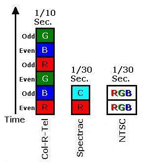
Compatiblility. Varying the field rate wasn't an option for Col-R-Tel. Col-R-Tel depended on capatibility with NTSC: Compatibility required matching NTSC's 60-fields-per second scanning rate. In favor of economical color TV then, Col-R-Tel had a serious flicker problem. As we said, Col-R-Tel's field rate matched the NTSC rate. Yet a new color frame occurred only 10 times per second. (That figure considers interlace. If we ignore interlacing, Col-R-Tel achieved 20 times per second, still flickery.)
The dim picture, another Col-R-Tel “weakness,” actually offered some relief. With a dim picture, flicker was less noticeable than with a bright picture. In fact, the Col-R-Tel filters considerably dimmed the picture. So much so that viewers had to watch Col-R-Tel in a darkened room. With a picture this dim, and a product this fun, maybe the flicker didn't bother most viewers.
Spectrac & the Two-Color Answer
Spectrac came on the scene in 1971. It posed a different answer to the flicker reduction vs. compatibility problem. Spectrac could draw a field 300 percent faster than Col-R-Tel could. The secret was that Spectrac only used two colors, instead of three. Instead of the primaries red, blue and green, Spectrac substituted red and cyan. This color swap accelerated the coloring process by 150 percent. Spectrac doubled this increase by only coloring each line once. In effect, Spectrac skipped every other line.
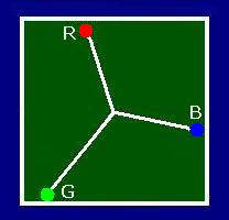
Why cyan and red? We perceive colors because our eyes are sensitive to combinations of the color primaries, red, blue, and green. In Spectrac, cyan worked because it's a mixture of blue and green. To reproduce flesh tones, “Spectrac red” might have been closer to red-orange than cherry red. By adding a small amount of green to the red, you achieve the desirable red-orange color. In color decoder terms, red passes through a phase-lead R/C or L/C network. Let's translate that for the viewer: Mr. Viewer, please twist the hue control. When the faces on the screen look right, you've finished your adjustments.
Flicker reduction. Could we reduce Col-R-Tel's flicker by cutting the number of primary colors? Yes, for two reasons...
|
|
The cost of this change? Two drawbacks come to mind. First, as in Spectrac, vertical resolution would drop by one half. The second drawback might be more noticeable: Two-color pictures offer a smaller range of colors (gamut) than do three-color pictures. The Two-Color GamutTwo vs. three-color gamut. The two-color gamut is a one-dimensional line between two complementary colors. Every color on the line is a combination of these two colors. The line can have height or width, but not both. In contrast, a three-color gamut is a two-dimensional plane with both height and width. This plane is really an array of lines just like the two-color gamut. Obviously this plane contains many more colors than just one line could hold. In theory, a three-color system can reproduce any color on the plane. Are two colors enough? Despite three-color theory, the reduced, two-color gamut is sufficient for many pictures. Commercial, two-color movies offer proof. These movies were popular for decades. Both Technicolor® and Cinecolor® provided film stocks for two-color movies. See Cinecolor. |
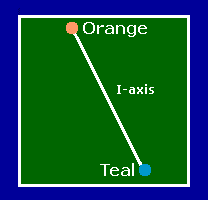
2-color TV can reproduce colors along a line between primaries. (Teal is bluish-green.)
|
|
Edwin Land's Retinex color theory supports the idea that two colors are enough. Land felt that the retina and cerebral cortex (the “retinex”) work together to fill in the missing colors. Land's experiments reproduced full-color images from only red and white light. Today, NASA uses Land's methods to enhance photos. Flesh tones. When you only have two colors, flesh tone accuracy is extremely important. Tests have proven that with correct flesh tones, the human eye forgives many color problems. For this reason, a TV must portray faces accurately, or at least naturalistically. The flesh of all races includes orange (or sepia). This fact is the basis for most “automatic tint control” (ATC) circuits. Such circuits generally reproduce colors in the yellow-to-magenta range as orange. |
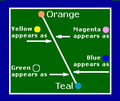
2-color TV approximates colors that are off the line between primaries. Color approximations are desaturated versions of the two primaries. |
Some ATC circuits go further, suppressing cyan, blue or green during scenes with faces. Along similar lines, classic mechanical television (MTV) sets used neon orange to reproduce monochrome pictures. Due to the narrow-angle nature of MTV pictures, faces were the most common subject. With its neon tube, even a monochrome mechanical television could reproduce faces in lifelike color. The dominant orange is a mechanical television legacy that NTSC picked up as its I-vector. As we'll see, the NTSC hue “I” reproduces as an orange-red color.
Go to Page: 1 2 3 4 5 6 7 8 9 Next
Page Directory
On this page...Col-R-Tel vs. Spectrac Col-R-Tel flicker Spectrac 2-color gamut
On related pages...
What is Two-Color TV? Two-Color TV History TV System Flicker Comparison 2.5-Color TV Gould Television: 3D from the Great Depression Gould 3D: Could It Work? Gould 3D: Camera & Monitor Formulas The Lost Creations of Leslie Gould Spectrac: Color for a Monochrome World