| • NOTICE. For more information on a topic, you may click the related footnote number. (Example: [24.]) |
Gould Television: 3D from the Great Depression
In 1930, most television engineers spent their time on refining the medium: Increasing picture size, brightness, and definition, or improving synchronization. But engineer Leslie A. Gould struck out in another direction, a startling direction: He designed two revolutionary technologies: (1) A cylindrical parallax barrier camera system, and (2) a 360-degree television display. [1.] Together, they could produce 3D images in full motion and color!
Better than holograms. Today, some people would call these images holograms. Others might think that Gould invented a volumetric display. Either invention would be achievement enough. But technically, Gould's pictures couldn't have been holograms or volumetric. Unlike the pictures from these two technologies, Gould's pictures would have been solid. A Gould picture would have maintained its three dimensions, even if the viewer walked completely around the television monitor. But like a hologram, a Gould picture would be autostereographic. That is, visible in the free air, without wearing headgear or glasses. [2.], [3.]
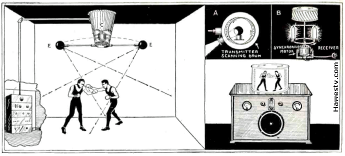
Artist's conception: Leslie A. Gould's 3-D, two-color television system. Solid-looking images in motion & color. [4.], [5.] |
About the Drawings
|
|
|
|
|
|
|
|
|
The Viewing Experience
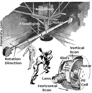
Gould's two-color picture would appear “inside” a 360-degree, revolving drum. (Item B in the drawing.) The 3D effect wouldn't require glasses. You could view the picture from anywhere around the drum. Gould's images were completely unlike a view through a stereopticon or View-Master. If you walked clear around Gould's screen, the image would be seamless.[7.]
|
World in a drum. Gould's little world wouldn't extend to infinity. The effect would end at the “ceiling,” “floor” and “walls” of the drum. [8.] Apparently, Gould's monitor wouldn't replicate the top or bottom of the image. For that reason, the view through the top or bottom of the monitor would be of the scanner internals: Not the scanned scene. Gould's system might distort sizes, as with a Mercator projection. |
|
||||||||||||||||||||
|
Red and green neon. Inside Gould's monitor, the red and green neon lamps would reproduce the image simultaneously. Each lamp would have its own amplifier. The two lamps would rotate inside the drum, but the lamps would be 180 degrees apart. The colored lines would scan down the frame near-vertically. One lamp would paint the back of the image, while the other lamp painted the front. [10.] |
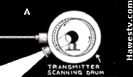
Gould cameras, in Popular Science [11.] |
Gould's use of complementary colors in his scanning lamps would make color rendition possible. The color method would be field-sequential: Just as in Peter Goldmark's CBS system, the Apollo mooncams, Col-R-Tel, and Spectrac. Since Gould's two colors scanned screen at the same time, the system might not seem field-sequential. Yet in Gould-3D, only one color at a time illuminated the same part of the screen. Gould's fields also overlapped. (That is, the fields were also frames.) Another difference from more familiar field-sequential systems: Unlike these color systems, Gould only added color to the monitor. The Gould cameras contained no color filters. [12.] For this reason, the reproduced colors were unlikely to be accurate.
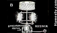
Transmitter as receiver. The Gould patent mentioned that the transmitter (cameras) could double as a receiver (monitor). [13.] To convert to monitor operation, Gould would have replaced the scanning photoelectric cells with neon tubes.
| Camera Head: Drum & Propeller Speeds (Example) | ||||
| FPS | Pixels/Line | Drum Slots | Propeller RPM | Drum RPM |
| 20 | 240 | 40 | 600 | 3,600 |
| Monitor: Drum Speeds (Example) | |||||
| FPS | Pixels/Line | Drum Slots | Drum RPM (CW) | Neon Tubes | Neon Carriage RPM, CCW |
| 20 | 240 | 60 | 1,800 | 2 | 600 |
|
Gould's 3D patent 2,058,681 cited the propeller and monitor figures above as operational examples of his invention. [14.] |
Variations
Gould's 3D patent described variations to the preferred implementation of his invention. For example, using one camera instead of two. The drawings to the right depict how this single camera would have mounted to the horizontal scanning motor. The points below summarize some of Gould's more prominent variations. [15.]
|
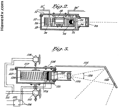
Gould's one-camera design for his 3D camera system (from U.S. patent #2,058,681) [17.] |
|
|
| Analysis: Turning the cameras outward would produce a panoramic view. (An “external panorama,” by Gould's definition. [23.]) Reproducing an “external panorama” might be a problem, though. The panorama would put the observer's viewpoint in the center of the scan. (The scanner would be blind at this point.) The monitor would display this “external panorama” inside-out. The resulting pseudoscopic pictures might appear unnatural.(The effect might be like looking through a View-Master after inserting the slide disc backwards.) |
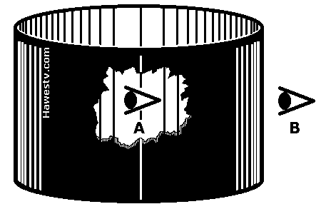
A: Viewpoint for “external panorama.” B: Viewpoint for “internal panorama.” Source: Author. |
|
On the other hand, external panoramas are wide-angle views. There is little parallax. The eyes see the horizon as flat. [24.] Then landscapes (external panoramas) have little depth. So, maybe the third dimension wouldn't be as important as the broadness of the vista. Yet according to Gould, one adjustment would be necessary, for sure: To display the panorama right-side up, the viewer should reverse the monitor drum rotation direction. [25.] |
|
|
Space mission panoramas. Such an “external panorama” camera might have been very useful on the Apollo moon-landing missions. (NASA photo) |
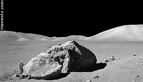
Astronaut, "House Rock," and moon rover, Apollo 16. |
|
Just imagine: A live panorama, from the Moon! NASA could have projected the images from the center of an auditorium. The screen would have completely encircled the audience. (Adjustments to the technology would have been necessary: Such as replacing the neon tubes with something more powerful, such as modulated arc lamps.) |
|
Could Gould 3D really work?
|
Gould 3D was ambitious, sophisticated, and ingenious. Yet an examination of the patents poses a few puzzles...
|
GOULD 3D: COULD IT WORK? |
Footnotes
1. Jason Geng, "Three-Dimensional Display Technologies," Advances in Optics and Photonics 5, 4 (2013): 456-535. doi:10.1364/AOP.5.000456] [See: https://www.ncbi.nlm.nih.gov/pmc/articles/PMC4269274/] •Re: Author studied PDF version of this article, which had different page numbers. (From 1 to 123). This version is available at same link. Of particular interest: [A] Description of cylindrical barrier displays (type of multi-view method), 8 to 10 & 12. [B] Drawing of two concentric cylinders (Equivalent to Gould's rotating neon tube bracket & counter-rotating scanning drum.), 72. Drawing of rotating LEDs, similar to Gould’s rotating neon tubes, 105. [C] Tables that critique multi-view systems, including cylindrical parallax barrier displays, 117-120.
2.
Leslie A. Gould, Television Apparatus and Method [3D patent], U.S. Patent 2,058,681
filed June 16, 1932, and issued October 27, 1936, 1, Column 1; 4, Column 2, claims 7 & 8.
Assignee: Radio Inventions Inc.
https://patents.google.com/patent/US2058681A/en?oq=U.S.+patent+2%2c058%2c681
•Re: Goals of Gould's patent: (1) Transmission & reproduction of 360-degree scenes.
(2) Either external or internal to a circle of view. (3) Reproduction as solid, 3D images.
(4) Cylindrical viewing screen. (5) Also reproduction of panoramic shots.
3. Ce Zhu, Yin Zhao, Lu Yu, Masayuki Tanimoto, eds., 3D-TV System with Depth-Image-Based Rendering (Springer Science+Business Media, 2013), Display types: 389-391, Multi-view: 396-397, Volumetric: 400-401. •Re: General discussion of 3D methods, distinguishing multi-view from volumetric displays. Simple illustrations.
4. N.A., “Television Projected in Three Dimensions,” Television News, May-June 1931, 132. •Re: (Graphic) Gould 3D, two-color television, illustrations & brief description. Reprint of Radio-Craft article below, but using different fonts.
5. N.A., “Television Projected in Three Dimensions,” Radio Craft, November, 1930, 277. •Re: (Graphic) Gould 3D, two-color television illustrations & brief description. Same article as in Television News (above), but reset in different fonts.
6.
Gould, Television Apparatus and Method [3D patent], 2, Column 2.
https://patents.google.com/patent/US2058681A/en?oq=U.S.+patent+2%2c058%2c681
•Re: Gould 3D television patent. Requirement that drums must be in phase &
in sync: Page 2, Column 2.
7.
Ibid. [3D patent], 3, Column 1.
https://patents.google.com/patent/US2058681A/en?oq=U.S.+patent+2%2c058%2c681
•Re: Gould 3D television patent claims: [His invention would reproduce]
“subjects whose entire outer surface it is desired to view.”
8. Ibid., [3D patent], 4, Column 2, claims #7 & #8. •Re: System scans 360° of cylindrical field. Yet top & bottom of scan are absent.
9. Ibid., [3D patent], 3, Column 2. •Re: Gould 3D patent gives drum & propeller speeds for example of Gould 3D system.
10. Ibid., [3D patent], 2, Figure 4, & 3, Column 2. •Re: One amplifier for each neon tube. Each tube scans image circle 180 degrees apart from other tube. Tubes scan roughly vertically, but with slight incline.
11. N.A., “New Television Camera Gives Depth Effect,” Popular Science, February, 1937, 55. •Re: (Graphic) Perspective illustration of Gould cameras at work, including detail drawing of camera internals. (For readability, author of this page has enhanced captions & callouts.)
12.
Gould, Television Apparatus and Method [3D patent], 3, Column 2.
https://patents.google.com/patent/US2058681A/en?oq=U.S.+patent+2%2c058%2c681
•Re: Gould 3D television patent. Refers to adding color at monitor: Page 3, Column 2.
13. Ibid., [3D patent], 3, columns 1 & 2; 4, Column 2. •Re: How Gould could convert either version of transmitter (cameras) to receiver (monitor).
14. Gould, Television Apparatus and Method [3D patent], 2, Column 1; 3, Column 2. •Re: Table of operational parameters for example of Gould's transmitter (cameras) & receiver (monitor). Why Gould's camera had different number of slots than Gould's monitor: Monitor drum & neon-tube bracket would have spun in opposite directions. Counter-spinning this way would allow slower neon rpm. Yet 40-hole drum (matching camera drums) would require unavailable main motor speed of 3,000 Hz. (In Europe, with 50-Hz current, this speed would indeed be available.) In U.S., with 60-Hz current, 3,000 Hz sync motor would require fractional pole pairs: Reason such motor would be unobtainable. Increasing number of drum slots to 60 would allow use of standard, 1,800-rpm motor with four poles. Line rate would match that of cameras, making 60-hole monitor drum effective.
15. Ibid. [3D patent], 1, Column 1; 2, column 2; 3, columns 1 & 2; 4, Column 2. •Re: Important variations in Gould's 3D patent.
16. Ibid. [3D patent], 2, columns 1 & 2. •Re: Single-camera version of Gould's 3D patent.
17. Ibid. [3D patent], 2, Column 2; 3, column 1. •Re: (Graphic) 3D patent proposes one-camera version of invention. Single-camera housing attaches directly to propeller motor.
18. Ibid. [3D patent], 3, Column 2. •Re: Version of Gould's 3D monitor that uses single neon tube.
19. Ibid. [3D patent], 3, Column 1. •Re: Scanning camera position can be above, below, or even with talent.
20. Ibid. [3D patent], 2, Column 1; 3, Column 1. •Re: Versions of Gould's 3D system that use different line & frame rates. Also variations that operate in different position with respect to talent.
21. Ibid. [3D patent], 3, Column 1. •Re: Patent claims that cameras may face outward (instead of inward, as at Illustration C). According to patent, outward-facing cameras would create an “external panorama.”
22. N.A., “New Television Camera Gives Depth Effect,” 55. •Re: Gould explains that cameras can face outward.
23. Gould, Television Apparatus and Method [3D patent], 1, Column 1; 3, Column 1. •Re: Gould defines “external panorama.” (Most people would just call this “panorama.”) But Gould distinguishes “internal panorama,” as space inside his cylindrical screen. When cameras point outward, we have “external panorama.” When cameras point inward, we have “internal panorama.” As cameras shift, audience viewpoint shifts.
24. Lenny Lipton, Independent Filmmaking, (San Francisco: Straight Arrow Books, 1972), 188. •Re: Parallax is difference between images of our two eyes. Parallax causes depth perception (spatial 3D). According to Lipton, beyond 100 yards, images of both two eyes are similar. For this reason, depth perception is nil, & 3D effect is unlikely.
25. Gould, Television Apparatus and Method [3D patent], 3, Column 2. •Re: To display external panorama on monitor that normally displays internal panorama, reverse drum rotation.
| • NOTICE. The Gould footnotes continue on parts 6, 7 & 8 of this series.) |
Go to Page: 1 2 3 4 5 6 7 8 9 Next
GOULD 3D: COULD IT WORK?
GOULD 3D: FORMULAS
GOULD's LOST INVENTIONS
GET A WHEEL
Page Directory
On this page...Gould Television: 3D from the Great Depression About the Drawings The Viewing Experience Variations Could Gould 3D really work? Footnotes
On related pages...
What is Two-Color TV? Col-R-Tel vs. Spectrac Two-Color TV History TV System Flicker Comparison 2.5-Color TV Gould 3D: Could It Work? Gould 3D: Camera & Monitor Formulas The Lost Inventions of Leslie Gould Spectrac: Color for a Monochrome World