Other Considerations
Sensitivity
Hi-Z Preamps. The signal coming off the phototransistor is very weak. As we've seen, a conventional preamplifier at this point helps to improve signal strength. A special, very sensitive preamp will work better than will a conventional preamp. The conventional preamp tends to load the input and actually loses some of the signal. The sensitive, or high-impedance preamp causes less loading. For this reason, a high-impedance preamp is very desirable. It will save one or two stages of conventional amplification. There are various types of suitable high-impedance preamps. We'll discuss high-impedance preamps with bipolar transistors and those with JFETs.
|
|
|
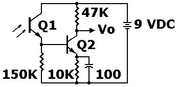
Schematic of high-impedance phototransistor preamplifier |
Hi-Z input bipolar amplifier. Today's bipolar transistors, even common replacement types, are capable of high-impedance operation. Few circuits exploit this fact. Some designers don't even know that they can get tube-like performance from a typical transistor. The transistor might not be operating at its peak gain. Yet the transistor can present to the load an input impedance of 100 kilohms or even 1 megohm. Compare that to the conventional transistor impedance of a few thousand ohms! But what about gain? Even high-impedance transistor circuits can produce more gain than can a triode tube or JFET! The output current from such a preamplifier is unusually quite low. To bring the current up to a useful level, you must consider the following stage. There you should use a Darlington device or a power MOSFET. |
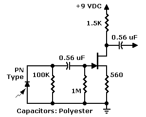
Unbiased photodiode with JFET preamplifier (Use with solar cell) |
JFET input. PN photodiodes such as the popular "bullet cell" put out an extremely low-level signal. Yet photodiodes offer advantages over phototransistors. For example, more rapid response to motion. Also, some photodiodes have a peak response in the range of visible light. On the other hand, most phototransistors provide peak response in the infrared. For color reproduction, flat visible light response is essential. Anyway, with photodiodes, a high-impedance preamplifier is even more important than it is with phototransistors. For such applications, the JFET is the amplifier of choice. A JFET is only a little more difficult to work with than is a bipolar transistor. Yet a JFET is more sensitive than either a bipolar transistor or a vacuum tube. Since the output of the photodiode is a high-impedance signal, the JFET is a helpful idea. A JFET adds complexity, but will probably save you a few amplifier stages. This page from Sharp Electronics includes more photodiode circuits: Sharp photodevice circuits. |
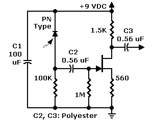
Reverse-biased photodiode with JFET photodiode with preamp (Use with small, PN diode) |
Coupling. The high-Z (high-impedance) transistor preamp allows resistance coupling (actually "resistance-capacity" coupling). In their amplifiers, the television pioneers used this same, resistance coupling. Because of their very limited drift, resistance-coupled amplifiers tend to be stabler than direct-coupled amplifiers. The low impedance inputs in normal transistor preamplifiers require electrolytic capacitors in the coupling network. When new, these capacitors are dreadfully leaky. As the capacitors age, the leakage only increases until it destroys the bias voltage on the transistor. At that point, the transistor will block and quit operating. Even before the bias deteriorates, the capacitor can visibly alter television signals. Yet with a high-impedance preamplifier, you can avoid electrolytic capacitors. Instead, insist on premium capacitor, such as the mylar or polyester types. Bypass. Coupling and bypass capacitors don't follow the same rules. In the FET preamp at left, notice bypass capacitor C1. You won't find a mylar or polyester capacitor of this value. No worry. For C1, a good-quality electrolytic capacitor is fine. Unlike C2 and C3 in the same drawing, C1 isn't in the signal chain. Instead, C1 is a bypass capacitor. C1 keeps ripple and noise out of the photodiode signal. For bypass and power supply filtering, electrolytic capacitors are adequate. Large-value, paper or oil-filled capacitors are fine, too. The problem with these electrolytic equivalents is finding one at a reasonable size and price. |
Go to Page: 1 2 3