|
|
|
The Pickup
Pickup Block. In the diagram above, Block 1 is our pickup device. For Block 1, many experimenters use a small solar cell or photodiode. Solar cells can pick up a fairly broad spectrum of light. If you use a solar cell, stick with a small one. Larger cells respond too slowly for this project. Photodiodes respond very quickly to light changes. Unfortunately, photodiodes require extra amplification.
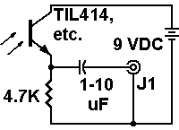
PhototransistorsEasy to use. My personal preference for Block 1 is a phototransistor. It's not as quick as a photodiode, but it offers some gain. Also, a phototransistor is more durable and easier to work with than a solar cell. See the phototransistor circuits nearby. You can use many types of phototransistors in these circuits. Two that I've used recently are...
|
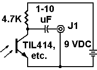 High-gain phototransistor circuit for mechanical video pickup |
Requirement: Clear case. Make sure that you use a
phototransistor with a clear, plastic envelope or
case. Types with black cases won't work for this project.
A black case blocks visible light. Some infrared phototransistors have
these black (or dark color) cases. Other devices have a clear case, and
respond to both infrared and visible light. These dual-purpose types
are fine. Radio Shack,
Mouser,
Digi-Key
and All Electronics
carry suitable phototransistors.
Install the phototransistor in a rectangular project box. Bud® makes suitable boxes. You'll find such boxes at Radio Shack, Mouser, and other vendors. The box must have plenty of room for your pickup and a preamp. Allow a couple of extra inches between the end of the box and the pickup cell. Of course, the box must not be too large to fit inside your scanner. The light pickup will face a window that you'll cut in one short side of the box. This side becomes the front of the box. In a moment, I'll give more details about the window. You'll mount your PC board in the back of the box. |
speed, but voltage gain of 0.9 |
The window should be about the size of our video picture frame, or slightly larger. Mount the phototransistor about two inches behind the window. The window and phototransistor must face the Nipkow disc apertures.
The Preamplifier
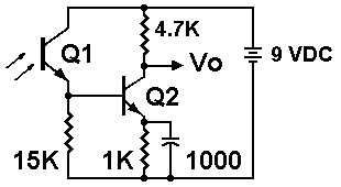
Preamplifier blocks 2 and 3 tend to be difficult for beginners to design and build. If you're determined, curious or persistent, forge ahead anyway. Beginners often surprise themselves with their success.How do we design a phototransistor preamplifier? We start by examining circuits. Maybe we can use or modify something that already exists. There are lots of circuits, and many are easy to build. Below is one idea that might help...
|
(Hfe: 200 or above. Germanium types won't work in this circuit.) |
phototransistor sensitivity |
|
Limits. The signal is still a high-impedance one. Yet we have a much stronger signal than we started with. At 1 kHz, Q2's unloaded gain is 179. Unfortunately, this is a pie-in-the-sky gain figure. When we connect Q2 to anything meaningful, our gain crashes back toward earth.
Capacitors. You'll notice the large decoupling capacitor. We need Paul Bunyonesque capacitors so that we can reproduce frequencies down to nearly DC. These frequencies account for crucial large picture details. Need: More Gain! Our new circuit is helpful for experiments. Yet we probably still need more voltage gain. I suspect that our solution requires two or three more transistors. On the next page, I explain how to add transistor stages. Believe it or not, there's a very easy way to do that! |
|
Go to Page: 1 2 3 Next
|
|
Index
Return to Top
Main mechanical television page
HOME
Pickup
Phototransistors
Preamplifier
Build Stage-by-Stage
Procedure
Construction Pointers
Troubleshooting
Use Preamp Designer