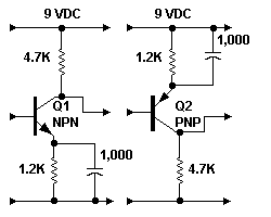
Build Stage-by-StageHere's an easy way to beef up that amplifier: "Tinkertoy" stages that you just snap together. Perfboard construction is fine for this circuit. Notice that NPN and PNP stages alternate. For the PNP device, use a 2N3906, 2N2907 or compatible device. Again, Hfe (beta) must be 200 or better, and the device must be silicon. You can add one, two, or several stages this way. Just follow each NPN transistor with a PNP stage. Then follow each PNP stage with an NPN stage. You'll need an LED driver to test the circuit with. Here's the LED driver circuit. |
give us the gain that we need. |
|
|
|
Procedure
Here's the design procedure...
- Add one transistor stage at a time.
- Then test the circuit revision with an LED driver. The only reliable test is a scanner test. Scan the LED and watch for some sort of image. The image doesn't have to be perfect. It must have contrasting areas, though. Reflected light falling on the phototransistor must cause the LED to flicker.
- As necessary, add stages one by one.
- After adding each stage, retest.
- When you get enough gain, stop adding stages.
- If you don't succeed after adding five stages, you have a wiring error. Quit and troubleshoot the circuit.
Construction Pointers
How do you know when you have enough gain? Easy. Plug the last stage into the input of the LED driver. Do the LEDs twinkle when they pick up reflected (not direct) light? Do the LEDs twinkle this way when you scan them? Good. Then you probably have the gain you need. Otherwise, repeat the design procedure.
Be sure to wire the stages correctly. Before switching on the power, check everything. A visual check takes far less time and costs less money than a smoke test! Make sure that you haven't reversed the PNP and NPN stages. You can damage some transistor types by reversing the collector and emitter connections.
Picture polarity. Some camera circuits produce positive-polarity signals. Our second schematic (page 1) is an example of this type circuit. Other circuits invert the polarity and produce negative signals. For example, see our first schematic (page 1).
Polarity effects. For our purposes, signal polarity is only important in the resulting picture. If we reproduce negative signals on the TV screen, the light and dark shades appear reversed. (In color TV, the colors might also reverse. That is, red appears as cyan, green becomes magenta, and blue becomes yellow.) Obviously the effect is totally unnatural.
Restoring positive polarity. We can easily restore a negative picture to its original polarity values. The trick is to run the signal through an inverting amplifier. At the output, a negative signal again becomes positive.
The US television system NTSC transmits negative-polarity TV signals. The advantage of this transmission method is that noise bursts appear in black. To the viewer, blacked-out noise bursts seem less distracting than white bursts. You can read more about picture polarity at Troubleshoot Negative Mechanical TV Pictures.
Go to Page: 1 2 3 Next
|
|
Index
Main mechanical television page
HOME
Pickup
Phototransistors
Preamplifier
Build Stage-by-Stage
Procedure
Construction Pointers
Troubleshooting
Use Preamp Designer