| Tweet |
|

|
Why Musicians Love High-Impedance Preamps
Loading drags down the output of your guitar or mic. The effect is muffled, indistinct sound with flattened dyamics. But when you play into a high impedance, your tone has heart. You're in the groove. You connect with your audience. What was fog is clear. What was dirt is clean. What was drab and featureless is now texture and distinction.
MPF102, RIP. Until recently, a JFET was the perfect answer: Here was a solid-state device with a sky-high input impedance. Plus, it offered a sweet sound that many compare to the ideal: The angelic tone of a triode vacuum tube. The power requirements were so modest that you could build a small FET preamp into a stompbox. The battery would last for many concerts and jams. Plus, the idea that a local store could supply a replacement JFET was another huge advantage of the JFET. Unfortunately, ease of replacement is no longer true of the JFET. The local Radio Shack store doesn't seem to carry JFETs anymore. You can order JFETs online, but the venerable MPF102 is becoming scarce.
But wait! There is an answer! Gather 'round...
|
|
|
Can't Find the FET You Need?
Go Beyond JFETs! Use High-Impedance Bipolar Transistors!
Time to don the thinking cap! Let's see: How about building a high-impedance circuit with normal transistors? You ask: “You can do that?” Answer: “Yes, you can!” There are two ways to go. But the circuits are unusual and mysterious. A tiny cabal of wizened engineers knows the secrets. Welcome!
I've built both experimental circuits below. Both seem to work, although I haven't tried them with a guitar on a noisy bar stage. (That test's on you.) Shhh! Here are the big, dark secrets...
- A normal, common-emitter stage with very large resistors: One transistor in an extremely simple circuit. The high-impedance performance will dazzle you. Very economical on battery power. Requires a high-impedance output or a follower circuit. The transistor should work fine into a tube guitar amp.
- A bootstrap follower, feeding into a normal common-emitter stage. The second stage provides all the voltage gain. To my ear, this circuit sounds better than the one-transistor solution. Building and debugging takes maybe a half hour more than for the one-transistor circuit. Also, the bootstrap circuit isn't as small as the one-transistor solution. The input impedance is likely higher than that in the one-transistor circuit.
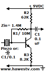 BJT stage with FET-like high impedance:
2N3904, 2N2222A, etc.
BJT stage with FET-like high impedance:
2N3904, 2N2222A, etc.
|
Other tweaks. I started with a 39K resistor in the collector. That's was roughly the value that the formula provides. The no-signal collector voltage of my first build was about 5.2 volts. This is quite acceptable. As I said, the circuit operates well. Yet the output voltage level wasn't perfect. Ideally this voltage should be about 4.5 to 4.95 volts. A lower collector voltage would allow for more voltage swing before distortion. Eventually I arrived at a 62K collector resistor and settled for an no-signal output voltage of 4.77 volts. Your results will differ from mine because of the differences between transistors. Below, this article provides a guide on how to tweak the no-signal output voltage. To bring down the collector voltage, I could have reduced the base resistor slightly. Another way to accomplish the same result is to reduce the emitter resistor value. (I'm happy with the circuit as it is.) Precautions...
|
Follower converts high to low impedance: 2N3904, 2N2222A, etc. |
|
- A general-purpose BJT isn't a low-noise device as a JFET is. You can certainly use a low-noise BJT in this circuit, but you'll have to hunt for one. Otherwise, a little grit isn't a bad thing. Maybe the noise will help to differentiate your tone. If you need the preamp to work and you can't find a FET, time to experiment with something new!
Tweaks. Tweaking the base resistor (R1) value is advisable. In this circuit, the value will vary according to the transistor that you use. I know: Resistors in the megohm range aren't exactly over-the-counter parts at Radio Shack. If you can't find the right base resistor, tweak one of the other resistors while meauring the no-signal quiescent collector voltage. Again, the ideal collector voltage falls in the range between 4.5 and 4.9 volts. Below is an easy how-to guide.
|
To raise the collector voltage... |
To reduce the collector voltage... |
|
|
| • NOTICE: Reducing the emitter or base resistor also reduces the input impedance. |
Formulas for Large-Resistor Preamps
This data might help (If not, skip ahead): I designed this circuit for transistors with a beta of about 200. Here's the formula for the base resistor value...
RB= [β x (RC + RE)]
Where
• β is the transistor's beta, a voltage gain of about 200
Resistances are in ohms
Example
• RB= [200 x (39,000 + 8,200)]= 9,440,000
• Round to nearest standard value: 9.1M (Note: I didn't have a 9.1M, so I used 10M. 10M is also close.)
The best base resistor value will allow a no-signal output voltage of about half the power supply voltage. A bit more than that is even better. Our one-stager has an input impedance of 1.4 megohm. Here's the input impedance formula for this circuit...
ZIN= [(β x (RE + RE-INT)) || RB]
Where
• β is the transistor's beta, a voltage gain of about 200
• Resistances are in ohms
• RE-INT = (26 / IE) in mA (Shockley's Constant)
• “||” indicates parallel, or the product over the sum
Example
• ZIN= [200 x ((8,200 + 273) || 10M)]= 1,449,044.8 Ω
If you require even higher impedance, you can use these values...
| For Input Z of 4.2M | ||
| R1= 33M (3-10M in series) | R2= 120K | R3= 22K |
Bootstrap Follower &
|
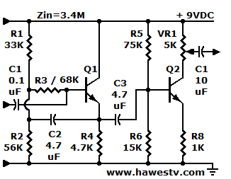
Experimental bootstrap amp for high impedance with common-emitter voltage amp stage: 2N3904, 2N2222A, etc. |
I built this preamp on a plugboard. I tested the circuit with a piezo pickup. First I directly coupled the piezo to the input. Then I tried the piezo into the 0.0033 uF base capacitor. I couldn't hear a significant difference in performance (and didn't expect any). I didn't test the volume pot, but that part of the circuit is conventional. It should work just fine.
Loading Remedy. I calculated the input impedance of the bootstrap amp at about 3.2 megohms. This is a no-load value, though. The output voltage preamp slightly loads the bootstrap stage. This loading will reduce the input impedance. You can considerably reduce the loading by increasing resistor values in the second stage by a factor of 10. Unfortunately, doing that increases the output impedance by ten times. If you're working into a tube amplifier though, the increase probably doesn't matter.
Bootstrap Formulas
Optional reading. For those who want to roll your own, below are some formulas for bootstrap parts.
ZIN Formula. Here's the input impedance formula for this bootstrap amp...
ZIN= [R3 / (1- α)]
Where
• α is the transistor's alpha, a voltage gain of about 0.98
• α (formula)= hFE / (hFE + 1)
• Resistances are in ohms
Example
• α = 200 / (200 + 1)= 0.995
• ZIN= [((68K || 56K || 33K) / 1- 0.995)]
• ZIN= 3.2 MΩ
•NOTICE. This formula assumes that the parallel R1, R2 and R3 are one-tenth of (β x R4) or less. If not: Parallel (β x R4) with the other parallel resistors!
Bootstrap CBOOT Formula. The bootstrap capacitor is C2 or CBOOT. The circuit's input voltage divider is in parallel with the bootstrap resistor. At the lowest desired frequency, CBOOT must short this parallel impedance. (So that the circuit will work for both guitar and bass, 20 Hz seems like an appropriate bottom frequency.) Here's the bootstrap capacitor formula...
CBOOT= [160,000 / (F x (R3 || R1 || R2) / 10)]
Where
• C= Capacitance in microfarads
• F= Frequency in Hz (lowest frequency)
• R= Resistance in ohms
• “||” indicates parallel, or the product over the sum
Example
• CBOOT= [160,000 / 20 x ((68,000 || 56K || 33K) / 10)]
• CBOOT= 4.7 µF (rounding to standard value)
Base Input Current IBB. The necessary input base current limits the size of the bootstrap resistor and input bias resistors. A bootstrap resistor must permit sufficient current for stable transistor operation. The practical IBB limit is about 10 times the minimum quiescent (q) current for the device. This minimum q-current is about IE / β. For the circuit on this page...
•IE is close to one milliamp.
•The β (beta or forward current gain) value is about 200.
•The minimum quiescent current is about 4.7 microamps.
Example
• RE-internal= Shockley's Constant: 26 / (1,000 (4.5 / 4700)) = 27 Ω
• IBB= 5.2 volts / (68,000 + 4,700 + 27)
• IBB= 71 µA: PASSES!
Loading. Again, consider reflected impedances. Loading the output of the bootstrapped first stage will affect the input impedance. Ideally, the output load should be 10 times or more as large as the first stage emitter resistor. The output load is the input impedance of the second stage. That is, the parallel combination of the base resistors. This parallel combination is also in parallel with the second stage's input impedance. To find this impedance, multiply the Stage 2 emitter resistor times β (beta). For the bootstrap circuit on this page...
Example
• Load= R5 || R6 || (R8 x 200), assuming a β of 200
• Load= 11,765 Ω
• Reflecting load in parallel with R4: 3,358 Ω
|
To find a Radio Shack store, click... |
Go to Page: 1 2 3 4 5 Next
|
▲ WARNING. This is your project. Your achievement is entirely yours. I assume no responsibility for your success in using methods on these pages. If you fail, the same is true. I neither make nor imply any warranty. I don't guarantee the accuracy or effectiveness of these methods. Parts, skill and assembly methods vary. So will your results. Proceed at your own risk. ▲ WARNING. Electronic projects can pose hazards. Soldering irons can burn you. Chassis paint and solder are poisons. Even with battery projects, wiring mistakes can start fires. If the schematic and description on this page baffle you, this project is too advanced. Try something else. Again, damages, injuries and errors are your responsibility. — The Webmaster |
|
Copyright © 2014 by James T. Hawes. All rights reserved.
•URL: http://www.hawestv.com/amp_projects/amp_hi_z_transistor/bootstrap-preamp.htm
|