|
|
FETs Aren't the Only Way!
BJTs vs. FETs. Thinking about adding a FET front end to your project?
Need a high-impedance input? FETs aren't the only way. Plus, FETs tend to be
extremely static sensitive, and they usually only have 10 percent of the gain
of bipolar (BJT) transistors.
There's another way. How about trying a high-impedance, BJT transistor
input? You might never have thought about that. Most textbooks stress
that BJT transistors are low-impedance devices. To that, I say this: You
must remember that impedance is just a ratio. It's the ratio of AC voltage to
current. If you reduce the current, the impedance rises.
|
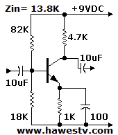
Low-Z Preamp
While transistors still draw current, you can control how much or little they
draw. For example, take a low-impedance circuit. See the illustration, right.
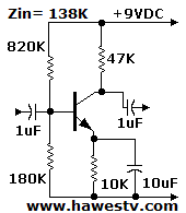
Converting this circuit to high-impedance is as simple as multiplying all
resistance values by 10. You then divide capacitance values by ten. For even
higher impedance (on par with tube amplifiers), use a 20X multiplier.
|

|
Converted, High-Z Preamp
The resulting amplifier is far more sensitive than the
low-impedance version. Yet you'll find that the new circuit won't have as much
gain as its low-impedance cousin: A transistor's beta (current gain) tends to drop as
emitter current drops. The amount of the drop varies with transistor type.
Gain. Also, by
Shockley's Constant, when you decrease current through the transistor, you also increase
the internal emitter resistance (Re-int). (In our examples, the internal
resistance rises from 33 Ω to 333 Ω. For our purposes, this difference isn't
important.)
In most cases, a bipolar version of the circuit will have more gain than a FET equivalent.
Although the FET version is a lower-noise circuit, the bipolar version is less susceptible
to static damage. (A low-noise transistor such as the BC549 might be appropriate for
critical applications.)
|

|
Coupling Capacitors
Plastic Capacitors: Good! Another very good idea is to switch from
electrolytic coupling capacitors to polyester, Mylar® or polypropylene
capacitors. We'll call these “plastic capacitors.” They're
reliable and reasonably stable. Plus, they pass very little leakage
current. Audiophiles prize them.
Electrolytics: Bad! On the other hand, electrolytic capacitors are
among the most unreliable devices in electronics. From the time that they're
new, they leak signals between amplifier stages. Sometimes this leakage is audible,
because it alters the bias and operating point of an amplifier stage. As the
capacitor ages, the leakage worsens. Arbitrary bias through leakage could even
shut down or lock up your high-impedance stage! The upshot?
Electrolytics have their place. They're great for power supplies and decoupling.
But as interstage coupling capacitors, electrolytics are terrible.
Fortunately today we realize the problem. And we possess the remarkable
technology of plastic capacitors. They save the day!
Capacitor cost. If the plastic capacitors cost too much, use ceramic
capacitors. The "C0G" type is the most temperature-stable. Epoxy encapsulated parts
are more resistant to moisture than are wax-encapsulated parts.
What if I must use an Electrolytic? Sometimes the low input impedance of
your amplifier demands an electrolytic capacitor. (Or at least some type of high
capacitance, small footprint capacitor.) In that case, use the best quality part
that you can find. Please don't resort to tantalum parts. In some cases, paper
capacitors will do. Most of the time, oil-filled capacitors, though of high
quality, will be too large. You might also want to consider a direct-coupled circuit.
|
|