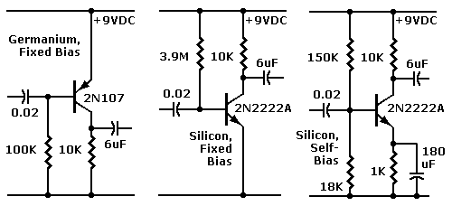
Necessary Circuit Changes
|
|
|
Advantages or Problems? Our part substitutions should properly bias silicon transistors in the original circuits. At least some of Mr. Buckwalter's circuits should now operate. Still, some of the circuits might develop new problems. Why? A little background helps: Germanium devices like Mr. Buckwalter's produce a very small current gain. The CK722 has a gain of about 10 to 30. The 2N107 has a gain of about 20 to 30. Today's “universal replacement” transistors such as the 2N2222A and 2N3906 offer a gain of about 200. The modern devices also have lower leakage. Modern devices operate over a much broader frequency band. And modern devices are far more sensitive than the older devices. The lower noise floor of the silicon devices helps most circuits to operate more quietly, too.
|
May alter operation. Yet these advantages don't make all circuits operate better with silicon. Replacing one transistor with a very different device can greatly alter circuit operation. You might as well try to replace a piccolo with a bassoon! Here are some examples of how device advantages can become circuit problems... |
CK722 |
- Higher gain problem. The germanium device was stable. The silicon device oscillates.
|

|
- Sensitivity problem. The germanium device biases normally with a base resistor of about 100K. For equivalent performance, the silicon device might require a base resistor of several megohms. The large-value resistor might be hard to find. (A better bias method is voltage-divider bias.)
- Noise problem. The germanium device generates audible hiss. The silicon device is much quieter, but might pick up noise such as radio waves or line hum. To eliminate such interference, you might have to add more negative feedback.
Go to Page: 1 2 3 4 5 6 7 Next