Today... Build Germanium Transistor Projects with Silicon Transistors!
Return with us now to the halcyon days of germanium!
Germanium transistor projects intrigued experimenters from the early days in the 1950s
until the early 1970s. In the Seventies, the higher-grade silicon devices began to take over the
hobby market. Hobbyists adapted, by attempting germanium-to-silicon conversions. Often, the
germanium circuits didn't cooperate. Several difficulties occurred. Fortunately, each one had a
solution. While the solution didn't always work, it usually did. This page describes the
conversion process.
Conversion Problems
Four Problems. In converting from germanium to silicon devices, you must solve four
problems...
Current gain. The rule of thumb is that silicon devices develop ten times
the current gain of germanium devices. (This statement is only true of small-signal
devices.)
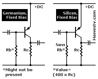
Leakage. Germanium devices often leak enough that they can bias
themselves. Silicon devices hardly leak at all.
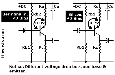
Bias voltage. For Class-A operation, germanium devices require a no-signal
bias of 0.3 volt. The equivalent Class-A bias for silicon devices is 0.7 volt.
Silicon device shape might differ from the germanium
device shape. The device pins might be in a different order.
Conversion Solutions
Current gain. In some circuits, more gain will be helpful. For example, the revised
circuit might be more sensitive than the original circuit. But sometimes, limiting the
gain (adding an emitter resistor, etc.) will be necessary.
Leakage. Bias by leakage won't be possible with normal silicon devices. If the
germanium circuit doesn't have bias resistors, you must add them. Otherwise, your silicon
transistor won't work.
Bias voltage. Correct bias is imperative. The main point of this page is rebiasing
your transistor base-emitter junction. The correct bias will allow the device to
amplify.
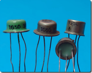
Silicon device shape. Package profiles have changed over the years. Expect
the silicon device to be a different shape than the legacy germanium part. We're
looking for reasonably similar behavior, not form. Often, the device pins will be in
a different order. With persistence and ingenuity, you'll be able to fit the new
device in the cabinet. You might have to shape the pins to fit the mounting holes
in the PC board.
The table below offers help with typical conversion
problems...
Conversion Method
Symptom
Problem
Solution (silicon circuit)
See Figure
Transistor distorts, or doesn't come on.
Improper bias for silicon.
If no base resistor, use value: Base resistor Rb = (400X collector resistor Rc).
If one base resistor Rb, change value: Rb= (400X collector resistor Rc).
If voltage divider (Vd) bias: Increase value of resistor to common (Rb2) until resistor drops 0.7
VDC between base and emitter. (Double or triple resistor value in germanium circuit.)
If the circuit has bias elements besides resistors, disconnect them. For example, some
germanium circuits include thermistors in the bias network. (These might be in addition
to bias resistors.)
1
1
2
Circuit blocks.
Gain of silicon transistor is way too high.
In one-resistor bias circuits, multiply base resistor Rb by about 20. Base
resistor Rb should = (collector resistor Rc x 400). Formula only applies
to circuits where Rb returns to power rail. See Figure 1.
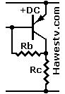
If base resistor returns to collector, instead of power rail (right): Rb= (Rc x 200).
Rc is collector resistor.
1
Circuit distorts.
Gain of silicon transistor is slightly high.
Eliminate emitter bypass capacitor Ce.
If no emitter resistor Re, add one. Resistor Re value should be 20% of collector resistor Rc value.
Add emitter resistor Re. Then adjust base resistors Rb1 & Rb2 as necessary. (See next
point.)
Necessary Adjustments:
•2-resistor circuits: Adjust resistor Rb2 value until it drops 0.7 VDC between
base & emitter.
•1-resistor circuits: Increase resistor Rb by one standard value until circuit operates
properly.)
2
2
1
1 & 2
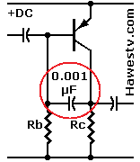
Circuit picks up radio.
Too much high-frequency response.
Solder a 0.001 µF, ceramic capacitor between the base and the collector. This
part will likely squelch the unwanted signal.
If not, replace the 0.001 µF cap with a 0.01 µF cap.
1 & 2
Assumptions
PNP: Silicon replacement is 2N2907 or 2N3906. (Or: device with beta= 200).
NPN: Silicon replacement is 2N2222 or 2N3904. (Or: device with beta= 200).
You may use other devices. But in 1-resistor bias circuits, you must adjust the base
resistor Rb value for correct bias. Device beta affects the value of this resistor.
Typically [Rb= 2 x (beta x Rc)]. Rc= collector resistor value.
Correct bias: DC, no-signal voltage on the collector should be about half of Vcc.
(Example: Consider an NPN circuit running on 9 volts. The normal collector voltage with
no signal on the base is 4.5 to 4.95 volts.)
•Figure 1. PNP amplifiers with 1-resistor bias
•Figure 2. PNP amplifiers with voltage-divider bias
▲ WARNING. The author assumes no responsibility for your success or failure in using methods on these pages. Further, the author
neither makes nor implies any warranty or guarantee as to the accuracy or effectiveness of these methods. Proceed at your own
risk.
♦ CAUTION. Avoid using the conversion method on this page for direct-coupled
preamplifiers, except for Darlingtons. To convert push-pull and complementary output
circuits, see Page
6. These instructions on this page are for single-ended amplifiers
that couple through a capacitor and resistor.
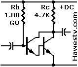
♦ CAUTION. Avoid using one-resistor (fixed) bias with Darlingtons.
With one-resistor bias, the device beta (current gain) determines the bias
resistor value. Darlington beta can be in the thousands or even hundreds of
thousands. For this reason, the bias resistor will be of impractical size.
EXAMPLE: You plan to use a Freescale MPSA13 Darlington. This device has a gain
of 200K. The collector resistor is 4.7K. Your base resistor will then be 2(200K x 4.7K),
or 1.88 billion ohms!
• NOTICE. For adventurous souls who want to build the above
circuit anyway: This example circuit probably wouldn't work, as the base
current might be less than the device leakage current. Leakage current and
beta differ from device to device. Beta also isn't a constant. It varies
within any device depending on device current and operation
frequency.
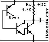
A potential use for this circuit is a temperature sensor. The circuit has a
thermal stability factor (SF) of twice beta, or 400,000. A desirable SF is 20
or lower. For this reason, the circuit would be useless as an amplifier. But its
thermal instability might make it valuable as a thermometer! I suggest substituting
the reversed BE junction of a 2N3904 transistor for the implausible 1.8 GΩ
resistor. See right for experimental circuit.