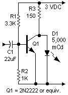
ASSEMBLY INSTRUCTIONS. Here's the simple step-by-step:
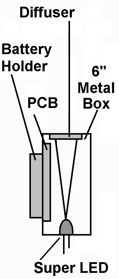
- Install the red, super LED in a diffuser box. Radio Shack's 6-inch long metal box is fine for the job.
- Mount the LED in one end of the box.
- Cut a picture-size window, facing the LED, in the opposite end.
- Fasten the electronics to the inside-top of the case.
- Secure two 1.5-volt batteries on the outside top.
- Connect the batteries, electronics and LED.
- Add a power switch.
- Cover the window with a diffuser. For similar projects, I've used diffusion glass from American Science Center. (See the company Web site.) A cheap substitute is a piece of milk bottle plastic. Interestingly, this works for an LED diffuser, but not for a phototransistor camera diffuser. For camera use, the stuff seems to block too much light.
- Glue the diffuser over the window with RTV (silicone) cement.
- When the glue sets up, check tracer operation. The LED's image should approximately cover the window. You might notice a few light rings, which are due to imperfect projection. You can move the LED and optimize the projection, or ignore the rings. The picture doesn't have to be an audience-pleaser. It's just for contrast and brightness tests.
- Temporarily position the tracer box behind the scanner.
- Prop up the window so that it faces the scanning surface of the disc.
- Jack the tracer into a CD player through a stereo, miniature phone plug. You now have all the electronics necessary for creating rudimentary pictures with your scanner. No, the pictures won't win awards, but they will be pictures.
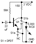
NOW IT'S SHOWTIME. Insert and play the NBTVA CD. At the CD player, adjust volume for best contrast. (The tracer doesn't have its own volume control. Why add complexity when the CD player comes with a control? You decide. If you want to add the control, go right ahead. And please write up your improvements!) With this tracer, some circuits may produce negative pictures. For those circuits, you'll need a phaser switch to invert the signal and return positives. The "deluxe" circuit achieves that result.
Go to Page: 1 2 3 Next

monitor circuit, too!

picture phase
