WHAT? You built a mechanical TV scanner and it's gorgeous... Until you turn it on? Then you get garbage or worse: Horrors! No picture! That's not mechanical television. That's maniacal television! Why, there ought to be a law!
NO! There ought to be a way to test your scanner! And now there is. A signal tracer solely for your mechanical television monitor. A tracer that you can build yourself in one evening. With one transistor. And it tests the entire signal chain, from CD output all the way to display input!
|
|
|
DESCRIPTION. This one-transistor tracer is a substitution amplifier for mechanical television troubleshooting. The tracer will aid you in testing the video circuit in your television monitor. I've designed the tracer for use with mechanical television monitor projects and similar monitors. The circuit substitutes for all the stages after it, including the LED display. Sorry, but although the tracer does a lot, it can't test your sync circuit. (Robotics hobbyists might find other uses for the circuit. Basically, it's an LED driver.)
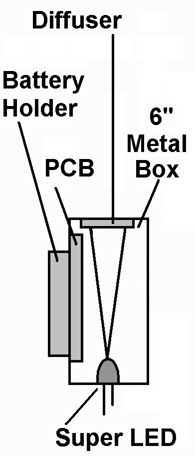
As the drawing indicates, you should mount this circuit in a box. I suggest RadioShack's six-inch, metal box. I tested the tracer prototype by connecting it to a CD player. Sure enough, the CD player can modulate the LED. I didn't scan the LED. Yet I strongly expect that if I had, I would have seen pictures. For best results, of course, you'll need a working sync circuit.
To achieve pictures, mount a diffuser over a window in the LED box. Position the box behind your scanner disc. Then play the NBTVA disc. More on this later.
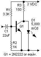
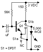
THE NEARBY CIRCUIT DIAGRAMS depict two versions of the circuit. I built the simple version on a plugboard. All parts came out of my junkbox. Builders that don't have all the parts can buy all of them at RadioShack. (Other vendors carry such electronic parts. I suggest... Mouser, Digi-Key, All Electronics, and Electronics Goldmine.) Many substitute, general-purpose transistors will also work in these circuits.
NON-ENGINEERS should stick to the parts values and power voltage that I've shown. After the circuit begins operating, an advanced builder can tweak parts values. The project, including optimizing values and testing, required about 20 minutes.
|
♦ CAUTION. If you use the deluxe circuit, stick with transistors that have a gain of 200. Use 2N2222, 2N3904, etc. Lower-gain transistors necessitate a resistor R1 reduction. Without testing the transistor, I can't precisely predict what the new value will be. If you want to experiment, do so at your own risk.) |
Go to Page: 1 2 3 Next

monitor circuit, too!

picture phase
