THE BASICS
- Where can I find a neon tube to use in my mechanical TV project?
- Can I hook a neon tube and disc to a modern TV set and get pictures?
- Can I hook a neon tube and disc to a modern radio and get pictures?
- Can I use a Nipkow disc to view modern TV shows?
- Can I play DVDs, videotapes, or iPod video on my mechanical TV monitor?
POINTERS
BUILDING COLOR MECHANICAL SETS
- How do I convert a monochrome mechanical TV system to color?
- How would I convert a black and white mechanical TV system to full color?
- Describe the simplest full-color system.
- Where do I get parts?
- What are some problems of color displays with only a few LEDs?
- Describe a derived-color system.
- I'm trying to build a derived, two-color system. I recorded the red and blue picture signals on a CD. Feeding the output to LEDs, I have a purplish picture. Even what was white looks purple. You said something about green being between red and blue. No matter where I move the brightness pot wipers, the color is still out of whack. How do I restore true color?
THEORY
QUESTION.Where can I find a neon tube to use in my mechanical TV project?
ANSWER. First, if you don't have a neon tube yet, save yourself a lot of trouble. Most hobbyists today use super LEDs instead of neon tubes. The flat plate and crater tubes of 1931 are antiques, and worth a lot of money. You could only acquire a neon TV tube (kino tube) from a collector. Sometimes, kino tubes turn up at at antique radio shows. The Antique Wireless Association hosts one of the largest annual shows.
If you're lucky enough to have a kino tube, it might not work. If it does, you probably don't want to wear it out. Crater tubes are even rarer than flat plate tubes. The LED situation is a different matter. Super LEDs are plentiful, and you can choose from a lot of colors.
Some hobbyists also use cold cathode fluorescent tubes. Hobbyists who build projection sets have tried lasers. Please don't use a laser in a direct-view set. It will blind the viewer! Still want to try a neon tube? You'll probably have to drive it through a step-up transformer. A reversed filament transformer should do the job. I once built a direct driver for a neon tube. I used a deflection transistor and ran it on rectified 120-volt line power. The gadget worked, but wasn't as bright as some LED displays.
QUESTION. Can I hook a neon tube and disc to a modern TV set and get pictures?
ANSWER. I know of no amateur disc that can produce useful pictures from modern, electronic TV. My own disc creates 24-line, sequential pictures. The TV in my den paints 525-line, interlaced pictures. Obviously, the two standards are far apart: Utterly incompatible. Fact: TV receivers must absolutely match the transmission standard. Precision is also an issue. With a milling machine, an expert machinist can make a high-resolution disc. Yet most of us can't.
To use a TV set source for mechanical reproduction, I recommend vibrating mirrors. Otherwise, go for a scan converter.
A scan converter is a load of digital electronics, or a dedicated computer. It will cost a lot of money, but it will work. You can use a pinhole disc with it. Yet before crafting the disc, check to see what disc specs the converter supports. Also, at the output of the converter, you must still have the LED driver. You also must still synchronize your scanning disc to the signal source. Otherwise: No pictures.
You can get a scan converter for mechanical television by two methods: (1) Buy one through the Early Television Foundation. Check Google for the web site. (2) Build the circuit from plans by the NBTVA. You must be an advanced builder, or know one. The circuit isn't for the faint-hearted. Also, several parts are becoming obsolete. One member has proposed a microcontroller version, and that would be simpler. I haven't seen any PC boards yet.
QUESTION. Can I hook a neon tube and disc to a modern radio and get pictures?
ANSWER. Some Depression-era radios included a jack for neon tube drive. In those days, you could indeed plug a neon tube directly into the receiver. The amplifier was widebanded enough to produce mechanical TV pictures on the tube. Of course, you had to synchronize your scanning disc to the station. As long as the station was local and line-synchronized, scanning disc sync would be easy. Your scanning disc also had to match the one in the station. In the US, typical line standards varied from about 24 to about 60. Many others existed, too. Also, the image polarity, rotation direction and scanning speed varied between stations. In 1929, the RMA proposed and passed regional standards. National standards waited for years. As you know, we still don't have international standards.
Modern radios can drive an LED display, and you can scan the display. The technique isn't as simple as plugging in a neon tube, though. (But almost.) My site provides a 12-LED circuit. You can build such a circuit with fewer LEDs and you'll still get a picture. The simplest circuit that I've come up with uses one transistor and one LED. The LED must put out at least 2,000 mCd of light. 5,000 is better. The top limit probably exceeds 80,000 mCd over a 90-degree dispersion angle. (Dispersion angle affects the extent of the illuminated area.)
The problem is programming. Here's the answer: The Narrow Bandwidth Television Association sells three or four CDs with programming. If your radio has a CD player, then you can play the CD through the radio and my circuit. Through some automatic or manual means, bring your disc up to sync speed. Now scan the LED with your disc. The LED must fill the entire frame evenly, so I recommend a diffuser. Operate the LED a few inches behind the disc frame.
QUESTION. Can I use a Nipkow disc to view modern TV shows?
ANSWER. Yes. You can use Nipkow disc reception with NTSC, PAL or SECAM transmissions. In between the receiver and the scanner, you must insert a scan converter. Early Television Foundation markets such a converter. The Narrow Bandwidth Television Association describes a circuit that an advanced builder can construct. See both sites. A Google search will turn them up.
A better (and cheaper) way to go is a program disc from NBTVA. This will run on a 32-line disc system. Also, I recommend using LEDs instead of a neon tube. Flat-plate and crater neon tubes are antiques. Nobody that I know of makes new ones. Anyway, LEDs operate better with solid-state circuits.
QUESTION. Can I play DVDs, videotapes, or iPod video on my mechanical TV monitor?
ANSWER. Yes. Insert a scan converter between your scanner and iPod, DVD or VCR. Also see my answer about playing TV shows through your scanner.
Aurora Design makes scan converters for 32-line mechanical scanners (and other line standards, too). With input video from an NTSC or PAL source, the converter outputs 32-line video. Feed the scanner output into an LED driver to illuminate your mechanical TV screen. Labguy demonstrates ideas and circuits that permit 32-line color mechanical television.
QUESTION: What are some easy sync methods?
ANSWER. I've designed a system that's self-contained. It syncs to itself mechanically. I use the same motor and disc for the camera and the monitor. With only one disc and motor, nothing can go out of sync.
Of course, you could also use synchronous motors at the monitor and receiver. Then the servo gain problem goes away. Unfortunately, sync motors tend to be expensive. How ironic. They used to be common. In the Sixties, every tape recorder and record player contained at least one synchronous motor.
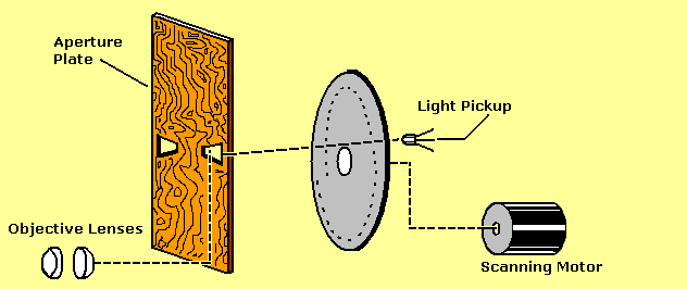
One-piece scanner: Camera parts. Mouse over for monitor parts.
QUESTION: Where can I find troubleshooting advice for my set?
ANSWER. Check out our troubleshooting pages.
QUESTION: How do I convert a monochrome mechanical TV system to color?
ANSWER. I know of two ways to convert a monochrome Nipkow disc TV to color. You'll want to see my mechanical TV color conversion Web pages.
- 1--Add a second amplifier channel. Use the same disc, but operate the electronics as if you have two, separate TV monitors. Now, you have a two-color system. One color can be red and the other can be green. Most scanners already have the red. Just add the green. If that works, you can add a blue channel. I have a version of the LED driver board with interlaced rows of red and green LEDs. I haven't experimented yet with full color. My derived color experiments worked. The green was too dim. I responded by writing color LED planning programs. One is on my web site. It helps you to work out how many LEDs to use in each channel. The three-channel, disc-based system is what Ives invented for AT&T in 1929. Unlike Baird's color system, the Ives system was practical, and could reproduce motion. Ives' system was the basis for the RCA color system.
- 2--Divide your Nipkow disc into three sections. Put a different color gel over each section. Switch to a white LED for the light source. Maybe add another white LED to make up for the gels. Now you have something like Baird's color system. This was the basis for the CBS color system.
If you have a color source for the monitor, then you just need to sync it up. The source could be a CD or a scan converter such as the NBTVA one. If you use a camera, then convert that to match the monitor. If you use the AT&T system, you need two or three pickup channels. Each channel must have its own color gel. If you use the Baird system, then your camera must have a Nipkow disc with color filters. The filter positions on the camera and monitor must match. To make the match, you'll need a commutator. Green should be the brightest color, followed by red and then blue.
QUESTION: How would I convert a black and white mechanical TV system to full color?
ANSWER. What you need are three copies of just the video part of the your circuit. Or you can use my circuit from the Web page. My circuit doesn't have gamma correction and DC restoration, though. The circuit works anyway. With direct coupling, you can eliminate the DC restoration requirement.
Run each color signal to its own amplifier. The circuit doesn't need to I and Q (or U and V) encode or decode the signals. You have plenty of bandwidth, because everything is closed circuit. The colors occur simultaneously. For that reason, you also don't need a field-sequential color wheel.
Of course, the input signal must be a color TV signal. Converting a black and white signal would be an experimental effort. The late Nam June Paik was a member of our Experimental Television Society. Nam pioneered artistic color conversions of monochrome, NTSC TV pictures. I believe that the results were surreal, rather than naturalistic. That is, an artificial process derived arbitrary colors. Nam's circuits tricked the NTSC color decoders into producing fake hues. But that's a horse of another color.
QUESTION: Describe the simplest full-color system.
ANSWER. The simplest system requires a camera with two phototransistors (or photodiodes) and two preamps. The monitor has two power amps and two super LEDs. The LED colors could be red and cyan.
In theory, if the red and cyan shades are just right, you can get full color. If you look at a color wheel, red and cyan are actually opposites. (Some people prefer orange-red to solid red. That's the idea behind the NTSC “I” video signal.)
QUESTION: Which two colors should I use, and why?
ANSWER. You'll need two colors that are on opposite sides of the color wheel. In color-wheel terms, we call such opposite colors “complements.” Mixing any two complements results in white. In television, some complements are better than others. For example, red and cyan are a better pair than yellow and blue. You can determine the best pairs from the proportions of each color in white. For example...
- Orange makes up 50% of white, and blue-green makes up 50% of white.
- Cyan makes up 70% of white, and red makes up 30% of white.
- Green makes up 59% of white, and magenta makes up 41% of white.
- Yellow makes up 89% of white, and blue makes up 11% of white.
Orange and blue-green is an excellent choice, although neither color is a primary. The NTSC “I” vector follows the orange and blue-green axis. Of all hues, orange has the best ability to render naturalistic flesh tones. (For all races, with the only difference being in saturation.) In pre-television days, orange and blue-green Cinecolor movies appeared in theaters.
With red and cyan, varying either color makes a lot of difference in the signal. These two colors are a fine match for color work. I suppose a 50-50 split would be better yet, as with orange and blue-green (above). Yet finding equally intense LEDs with the same viewing angle is difficult. The downside of a red and cyan combination is that flesh tones might appear too rosy. Another problem is that bright cyan LEDs aren't as common as bright red LEDs.
Green and magenta should work. A green and magenta vector is part of the NTSC television signal. Color TV sets phase shift, detect and decode this "Q" vector. Finding the right shade of magenta LEDs would be difficult. Advantage: Grass looks green. Disadvantage: Faces look purple.
Now let's consider yellow and blue. Most of the picture is in the yellow signal. Since you can't individually vary red or blue, you lose control of a lot of the picture. Variations in blue only account for 11% of the picture, which isn't much. Plus, you see jaundiced, yellow faces. (Yet the sky looks blue.) Obviously, red and cyan are a better choice than yellow and blue.
QUESTION. Where do I get parts?
ANSWER. Believe it or not, most of the parts are still out there. Unfortunately, parts aren't as cheap as in 1928 to 1934, the day of mechanical TV. Try Mouser and Digi-Key for transistors, resistors, diodes, capacitors and coils, perfboard, etc. See my Mechanical TV Links page for surplus vendors for wire, wall wart power supplies, PC board stock, chassis, cabinets, connectors, etc. If you insist on building with tubes, try Antique Electronic Supply. You're on your own for the disc and disc cabinet. Kodak sells Wratten filter material, but it's very expensive. Rosco sells filter material at more reasonable prices.
QUESTION: What are some problems of color displays with only a few LEDs?
ANSWER. Unless you're lucky, you can't make real-world LEDs match your mathematical design. If you use just a few LEDs, the calculations indicate that the intensities are off. You see, you can't correct for fractional LEDs. Instead, your calculation must round to the nearest LED. Rounding introduces an intensity error. Depending on your LEDs, this error might be small or large. Fortunately, you can ignore small errors.
Also, you must include a "fudge factor." This fudge factor makes sure that you never round to fewer than three LEDs. (In the case of a two-color display, that's two LEDs.) Well, the fudge factor necessarily throws off your color accuracy. But the possibility of full color is more important than perfect accuracy. Anyway, you can tweak color intensity with brightness pots.
I wrote a script that performs all these calculations for you. After you have your numbers, you should apply common sense and examine the results. See if everything rounds out the way it should.
You should know that the program doesn't compensate for viewing angle or off-axis transmission. Your best bet is to buy LEDs with nearly matching viewing angles. After mounting them, adjust them for even illumination. You might need to rotate some of them until you get the transmission axis right. Rotation can make a huge difference.
QUESTION: What are some advantages of two-color video systems?
ANSWER.
- Substantial flicker reduction in field-sequential pictures. This is an issue for NTSC, but not for 12.5 fps pictures. A 12.5 fps picture already has plenty of flicker. Dividing this 12.5 fps by two color fields only worsens the situation. Now you have a terrible 6.25 Hz, full of flicker. Consider a two-color wheel, though. I have a friend who succeeded big time with two-color, field-sequential equipment.
- Dropping to two colors reduces your bandwidth requirement by a third.
- The bandwidth of only two channels is narrow enough to fit on a CD. You can skip the field-sequential and use simultaneous color. Now, we're really talking reduced flicker!
- Two channels are easier to play back than three are. You have two channels on your CD. Two channels fits two colors just fine. No need to fiddle with derived-color matrices!
- Two-color systems have fewer electronic circuits to build, adjust and repair.
- Two-color systems are less expensive to build and maintain.
- Two-color systems go together faster.
- Fitting two pickups behind a lens and evenly illuminating them is easier than the same task with three pickups.
- Two colors don't necessarily limit your color gamut. You can derive a third color at the monitor. The only cost is one more LED driver.
- A derived third channel is every bit as good as a camera-originated channel. In fact, maybe derived color is superior to transmitted color. Derived color suffers no signal loss over the cable or transmission route.
QUESTION: Describe a derived-color system.
ANSWER. To begin with, I don't have a color, narrowband CD. I made derived-color pictures with an experimental camera. The derived color experiment only required one preamp. I used two power amps (LED drivers), though. I connected my two LED drivers to the same preamp. I then operated the drivers out of phase with each other. One driver lit red LEDs. The other driver lit green LEDs.
All the shadows were one color, and all the highlights were another. The two colors only mixed occasionally. The mixed color was yellowish. My red LEDs were too strong. As a result, the yellow also had pink in it.
I used two colors because that way, I only needed two power amplifiers, instead of three. Besides, blue only makes up 10 percent of the picture.
Lots of people, including Baird, experimented with two-color systems. The most recent was Topping's NTSC-based system in 1971. With field-sequential, flicker reduction is at a premium. A two-color NTSC system has the same flicker frequency as with monochrome! If you use a bluish green (cyan), nobody notices the missing blue. Well, maybe not. NTSC employed this technique with the original I-signal (orange and cyan). Unfortunately, most TV sets can't receive the entire I signal.
QUESTION: I'm trying to build a derived, two-color system. I recorded the red and blue picture signals on a CD. Feeding the output to LEDs, I have a purplish picture. Even what was white looks purple. You said something about green being between red and blue. No matter where I move the brightness pot wipers, the color is still out of whack. How do I restore true color?
ANSWER. If you remove green from RGB color space, then you can't make white anymore. You could look at the scene in black and white. Then you'd see white. Otherwise, in additive color renditions, white remains the sum of R, G and B. Remove green, and you have some combination of red and blue. That should look purplish, rather than white. I think that you're seeing the purple.
You're closer than you think to restoring those whites. Purple (or magenta) is the complement of green. To convert purple to green, invert the purple signal. Add an op amp, transistor or tube to handle the inversion. Then send the inverted magenta signal to a green LED.
QUESTION. Why don't equal amounts of two complementary colors make white?
ANSWER. An equal mix of complements doesn't produce white because we perceive some colors as brighter than others. For example, a green appears brighter than a red with same saturation value. A blue appears dimmer than a red with the same saturation value.
The HSB (hue, saturation and brightness) color model for TV considers perceived brightness: Because of perception, three-color TV builds luminance from different amounts of three additive primaries. White is maximum luminance. Here are the quantities of the three primaries for TV...
| Red | Green | Blue |
| 30% | 59% | 11% |
The perceived brightness rule applies to complementary colors, too. Some complements are secondary colors, while others are primaries. This fact doesn't effect perceived brightness. The eye might still perceive one complement as being brighter than another.
QUESTION. Can two complementary colors both be primaries?
ANSWER. No. When you have a pair of complements, either but never both can be primaries. Yet both complements can be secondaries. For example, the most famous and most useful complementary pair in NTSC TV is the I axis. This axis runs through the colors orange and blue-green. (Blue-green is sort of a dark cyan color.) Both colors on the I-axis are secondaries.
QUESTION. Why is orange such an important TV color?
ANSWER. The eye is most sensitive to hues in the orange or plus-I area. This area includes the flesh tones for all races. (Differences between flesh colors for any two races affect color saturation, but not hue.) Early NTSC TV sets reproduced extra detail in the I-axis colors.