ADVANCED QUESTIONS & PROBLEMS
PROBLEM. I want to use the LED driver with the line output of my CD player. How would I do that?
ANSWER. You might need an LED driver with more sensitivity than my circuit has. I designed the driver to work with a CD player's earphone jack. Usually the line-out jack is a much higher impedance source than the earphone jack. Your line output might not provide enough current to operate my LED driver.
You can adapt this project for use with a line-out jack. I recommend adding one or two preamplifier stages. If your stages invert, but you need positive video, use two stages. Otherwise, you might reproduce negative pictures. On the other hand, with some CD players, inversion might be useful.
The adapter must have a high-impedance input. If you use coupling capacitors, they can be fairly small, say 1 µF or less. Then you can avoid electrolytics and the damage that they do to your images. Use the best quality capacitors that you can afford. In such circuits, polyester film capacitors perform well.
Try an emitter follower circuit. An emitter-follower offers substantial impedance gain, but no voltage gain. The emitter follower also won't invert your picture phase, a great advantage. A small-signal Darlington is another way to make a preamp with a high input impedance and a moderate output impedance. I recommend the Freescale (Formerly Motorola) type MPSA13. This device is similar to the Fairchild 2N6427 and 2N6426. All these devices are excellent. In gain, the 2N6426 version has the edge.
The reason for using a Darlington isn't extreme voltage gain. In a solid-state line adapter, impedance gain is more important. Depending on your CD player, the line-out impedance might be as high as 100 kilohms. The adapter must convert this impedance down to a few thousand ohms. This impedance spread might be too broad for a conventional emitter follower circuit. Yet a Darlington circuit can handle this wide impedance spread. Another option is to use a JFET. A JFET circuit could provide the impedance match, plus a small voltage gain. For an example JFET circuit, see this page: JFET Preamp. This JFET circuit is an inverter.
CD players differ quite a bit. Adapter specifics depend on the player that you have.
PROBLEM. I tested this circuit on a Spice simulator. For modeling purposes, I used a single LED, not the array. Linearity and frequency response are poor.
ANSWER. You didn't really test my circuit. By changing the display, you created a different circuit. Your conclusions apply to that circuit, not my circuit. Arbitrary changes to the amplifier load caused the poor linearity and frequency response. If you vary the number or type of LEDs, of course the circuit won't perform well.
|
Consider the following example (right)... Here are two simple transistor amplifiers. With no signal, the left amplifier's output voltage is about 6.6 volts. This is the quiescent collector voltage for the circuit. The quiescent emitter conditions are 1.2 volts at 1 mA. Differences. Except for the collector resistor, the right amplifier is the same as the left amplifer. By changing the load resistor to 100K, I've shifted the emitter and collector voltages. For instance, the quiescent collector voltage now measures 11 volts. (I tested that by building the circuit.) |
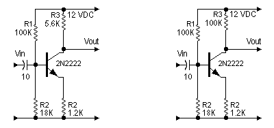
|
Left Amplifier Analysis. With an an input sinewave on the left amplifier base, here's what happens: The collector output rises above or falls below 6.6 volts. Of course, the amplifier increases signal level and inverts the signal. Because the output is roughly centered, the chances of clipping are small. (The emitter voltage shifts the collector voltage upward a bit, but not significantly. In return, emitter feedback tends to improve fidelity.)
Right Amplifier Analysis. Now, we apply an input sinewave to the right amplifier base. The collector output rises above or falls below 11 volts. Again, the amplifier increases signal level and inverts the signal. Unfortunately, the output is far off center. The chance of clipping is likely. (The large collector resistor upset the circuit's base bias.)
- A negative input signal easily cuts off the collector signal. Remember that the collector quiescent voltage is 11 volts. The collector only needs to rise by one volt.
- The amplifier clips negative peaks and outputs flat-topped positive peaks.
- In the positive direction, this amplifier has a lot of gain. A positive input signal can cause the collector to drop 11 volts. Compare that to 5.4 volts for the left amplifier. Unfortunately, the right amplifier's output waveform is terribly assymmetrical.
- I can vouch for the clipping effect. I demonstrated it. I wired this amplifier to a signal tracer. Then I used the circuit as a microphone preamp. I could hear the output distortion.
Now, back to the LED driver. By substituting one LED for my display, you introduce similar problems to those in the example above. I designed the LED driver to output 80 milliamperes average to 12 LEDs. You substituted one LED. This LED probably requires 20 mA. (That depends on what LED type you used.) The result? You overdrive the LED. Why? Because you aren't using the rated load. Driver gain doesn't change, but load resistance increases. No wonder fidelity and linearity are poor. Your "simulation" guarantees that result. Also, you don't mention a series limiting resistor for the LED circuit. If you forget the resistor, the LED is toast.
Input Voltage. Now, let's talk about input voltage. I don't know what voltage you're using for the input. Did you use the NBTVA club standard of 1 volt? Then you've probably got the CD volume up too high for this amplifier. To turn on, the PNP input transistor junction requires about 0.7 volt. For normal bias without a signal, the bias network gives my transistor 0.7 volt. (Because this is a PNP transistor, the polarity is really -0.7 volt.) This quiescent voltage turns the LEDs on halfway. The signal adds to or subtracts from this quiescent (no-signal) bias.
If you want the quiescent bias to be some other level, I leave the modification to you.
PROBLEM. I tested this circuit on a Spice simulator. I used "generic" transistor models, not the parts you prescribed. I see lots of nonlinearity. With a 1-volt drive signal, the model predicts bad behavior. At anything above 0.25 volts peak input, the circuit saturates.
ANSWER. What you analyzed isn't my circuit. Use the specified parts, or expect the circuit to misbehave.
I don't know what type of transistors you substituted in your simulation. Since your circuit saturates at 0.25 volts, I suspect germanium transistors. Germanium devices turn on at 0.25 to 0.3 volt or so. This is the difference voltage between the base and emitter. Saturation occurs at some higher voltage. Silicon devices turn on with a difference voltage of 0.7 volt. This is the proper bias voltage for class-A operation. If you expect the best performance, be sure to use silicon transistors in this circuit.
As to the fidelity criticism, you have the fancy software, and maybe that tells you something I don't see. I can't speak to that. I don't have the software. I just built the circuit.
If you insist on a 1-volt input signal, here's a suggestion: Maybe you need to fire up that Spice simulator and design an attenuator. Whatever floats your boat. I'd just twist the volume knob on the input CD player.
PROBLEM. I tested this circuit on a Spice simulator. A "324" integrated front end would work better.
ANSWER. If you have a design that you think is superior, then build it. Experimenting is one of the best ways to learn and to achieve good results. Still, I suggest that you consider more than fidelity. This design has a basis in the original Daven television circuit. This circuit offers the same advantages as that circuit. A lot of builders want these same advantages today...
- Easy and quick assembly from common parts.
- Fairly good peformance under typical conditions.
- No fussy adjustments.
- The simplicity and reasonable operation of a hobby-type circuit.
- Dependable performance.
- Easy maintenance.
Using an integrated circuit as a simple level shifter seems like overkill. Consider that some CD players can probably drive an LED without an external amplifier. In 1928, engineers only needed three tubes for such a circuit. They'd be amused that for the same task, we need scores of integrated transistors.
My LED driver isn't an engineer's dream. I admit it. Instead, my circuit's a fun project that you can easily use, build and modify. My circuit is capable of making moving images. You might like it. On the other hand, if you're an engineer and you can use CAD simulators, then you're more advanced. Congratulations. You don't need this circuit in the first place. Sorry to waste your time.
By the way, the "324" isn't the best op amp for this circuit. Peter Smith uses TL072 or TL082 ICs because they have superior characteristics for club mechanical video projects. The TL072 and TL082 have high-impedance mosfet inputs and offer a high slew rate. These ICs also have a much better gain-bandwidth product (GBP) than the 324 does. In fact, in terms of GBP, a 2N2222 or 2N2907 transistor beats all these ICs.
| Amplifier | LM324 | TL082 | 2N2222 |
| GBP | 1 MHz | 10 MHz | 300 MHz |
You might have chosen a 324 op amp because it only requires one power supply. In that case, I suggest using a TLC272 op amp. This single-supply, CMOS op amp has a high impedance and a medium top frequency. The TL072 offers a better GBP and top frequency. Yet the TLC272's GBP and top frequency are much better than what the 324 offers.
QUESTION. This circuit inverts. Does the club video standard specify inverted video?
ANSWER. Yes, the circuit inverts. So did the Daven circuit that I based this one on. I assume that your question about NBTV specs is rhetorical. The answer is no. Club specs call for positive video. If you want positive video, you can start with a fresh circuit. Or you can add an inverter to my circuit.
Also, remember that the input source is probably a CD player. You might not know that many CD players invert. If you have one of these inverting CD players, then my amplifier corrects the inversion.
An even easier way is to flip the input cables.
PROBLEM. This circuit provides too much gain. To fix that, you should add (or increase) an emitter resistor, etc...
ANSWER. Yes, you can change the gain by altering the bias resistors. Unfortunately, transistors are less forgiving of resistor changes than op amp chips are. Op amps have internal bias circuits. Transistors don't. Result: When you change the resistors in a transistor circuit, you can alter both gain and bias.
Why should you care about affecting the bias? Because with the bias change, your transistor stage gets a new operating point. Now the stage might not work well or at all. I leave you to study up on that. Bias is something that few technical people understand anymore. Do they teach bias in school anymore? I wonder.
By the way, there's an easier way to cope with the extra gain: Use the CD player volume control.
QUESTION. The input capacitor seems too small. Isn't that capacitor contrary to the idea of preserving the low frequencies?
ANSWER. Yes, the capacitor is small, and any capacitor will cause phase shift. Why do you care? Because phase shift distorts the image.
If you want to preserve low frequencies, then use a direct-coupled circuit. Notice that except for the input circuit, this circuit is direct coupled. You can restore DC to the output by installing a clamp circuit. This circuit is outside the scope of this project, but NBTVA provides diagrams. DC and low frequencies appear in your images as large picture details. For example, backgrounds, image outlines, or dark grays.
DC-restorer diagrams also appear in 1970s TV textbooks. Originally these clamps were fairly simple circuits. With today's engineering, you'll need a pocketful of ICs to build one.
You probably wonder why I didn't use a larger input capacitor, say an electrolytic. Because all electrolytics leak current. The leakage causes artifacts in the image, and these can wreck an NBTV picture. Direct coupling or a DC restorer clamp is the way to go. If your CD player permits you to couple through a resistor, then do that. But beware: If you operate the player on AC, it must have an isolation transformer. Otherwise, you might get a lethal shock. If you survive, you might also damage the player or your mechanical scanner. Also, if you're running your CD player on batteries, it must be able to source enough voltage and current to operate your scanner amplifier. If not, you risk burning up the final stages of your CD player. These are reasons why I used a capacitor to isolate scanner electronics from the CD player.
- To achieve operation with a one-volt peak signal, you could attenuate the input signal. Your attenuator could be very simple. Two series resistors across the CD player output would do the job. Make sure that the total value of the resistors isn't less than the output impedance of the player. Otherwise, you'll load down the player. Loading could damage the player. Take the input to the driver circuit off the junction of the two resistors. For example, suppose that the player normally works into 100-ohm headphones. You could use two 56-ohm, half-watt resistors in series. Adjust the output to 1 volt. Take the input voltage off the resistor junction. At the junction, you should see half-volt peaks. For quarter-volt peaks, make the divider with a 75-ohm and a 27-ohm resistor.
- Want a noninverted output? Add an inverter stage to the input. This stage would be an NPN transistor. At the same time that you add the NPN device, also add an emitter resistor to the PNP device. The NPN device replaces the base resistors on the PNP device. Of course, the NPN device requires its own base resistors. I'll experiment a little and see what I can come up with.