 Mechanical TV receiver: Mouse over parts.
| Tweet |
|

|
Paul Nipkow's Box of Dreams
MECHANICAL TV was once the only television. It started as an epiphany on Christmas Eve, 1883. That day, a young student, Paul Nipkow, dreamed up his Elektrisches Telekop, the simplest mechanical TV system. In 1884, he received German patent 30,105 for this earthshaking invention. According to historian Albert Abramson, this is the “master television patent.” As the century turned, Constantin Perskyi, a Russian, actually named the device “television.” Using Nipkow's design as a model, several inventors replaced electrical components with the new electronics. For example, the Moore Lamp substituted for the Faraday Effect light valve. A de Forest amplifier and an Elster and Geitel photocell supplanted the passive selenium pickup. Yet many TV devices retained Nipkow's mechanical scanning discs in both the camera and receiver.
Only for Closeups
DEBUT. Scant years later, television was ready to pop out of the lab and drop into the home. Between the world wars, mechanical television debuted on peephole sets. These sets were little more than prototypes, but they incited a craze. Because the sets could only display closeups, faces were the most likely subjects. Tiny TV pictures glowed red-orange, the best color for rendering those faces. Meanwhile, on-screen shadows appeared in gray and black. Depression-era viewers were short on cash, but long on ingenuity. They built their own sets on kitchen tables across the world.
What Could I See on Mechanical TV?
FLEDGLING TELECASTERS provided an incentive to “look in.” In 1928, experimental TV stations began transmitting Vaudeville skits, puppet shows, lectures and musical presentations. Charles Jenkins received the first US TV station license on February 25, 1928. Jenkins' station was W3XK. The station location was Washington, DC. Other stations opened up in cities all over the world. At first, TV shared the AM (medium wave) band with sound radio. In England, mechanical TV remained on the medium waves. Yet in 1929, the U.S. government designated a new shortwave TV band. This new band allowed for broader channels than those on the medium waves. A broad channel supports fine picture details. Most U.S. stations moved to the new band. There, broadcasters could increase picture definition for more pleasing and natural images. At last, two actors could appear together in one TV picture (“two-shot”). Since most TV shows are about relationships, two-shots were a breakthough!
THE SCREEN GROWS. Not everybody liked peephole TV, though. Fortunately entrepreneurs and engineers were constantly improving the medium. Soon, manufacturers released consoles with 10 by 14-inch screens. U.A. Sanabria thrilled New York cinema patrons with his projection television system for large audiences. A color mechanical television demonstration took place 25 years before electronic color TV entered homes. Even the ballyhooed 1928 color system wasn't the first color mechanical TV. A Russian, A. A. Polumordvinov, patented the first field-sequential color system in 1899. (Russian patent 10,738.)
|
Neon Tube & Scanning DiscMECHANICAL TELEVISION RECEIVERS had no picture tubes. Instead, a flickering neon glow tube illuminated the screen. Fifty thousand times a second, a new flicker initiated a different gray value. Behind the screen, a motor spun a scanning disc. Disc apertures distributed gray values over the screen, thereby reproducing pictures. To the viewer, pictures appeared to float on the disc surface. Other mechanical sets substituted a drum or vibrating mirrors for the disc. TYPICAL DISCS were aluminum or cardboard, and from one to three feet across. Later, engineers succeeded in using disc real estate more efficiently. Next generation mechanical sets incorporated smaller discs with lenses. Some sets required the viewer to manually synchronize pictures. This task actually wasn’t hard. As with channel surfing today, viewers accepted synchronization as part of the entertainment. Later sets responded to sync signals, or incorporated line-synchronous disc motors. |
MOST EARLY SCREENS supported pictures the size of a matchbox. Some receivers included magnifiers. These sets achieved postcard-size images. Later mechanical devices made possible screens as large as we have today. Even in 1927, Herbert Ives at AT&T displayed a two by three-foot picture.
COARSE-GRAINED. At first, TV pictures appeared coarse-grained. Due to government regulations, pictures from early equipment consisted of some 24 to 60 lines. Picture detail topped out at less than three percent of what we enjoy today. Yet even these low-definition pictures could display recognizable faces. Later mechanical television devices yielded resolution exceeding the specifications of today’s television. Manufacturers such as Western, Daven, Pilot and Peck sold television kits and sets.
A Manufactured Set
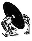
ABOUT THE PHOTOS. Above are photos of a 1932 set from Globe Television & Phone Corporation (185 Devonshire Street, Boston, MA 02110-1407). (1.) This advanced mechanical TV displays 60-line pictures from the 100 to 150-meter TV band. The set includes an eight-tube, wideband radio receiver, plus a neon crater tube. The crater tube and its accompanying lens disc are improvements on the flat-plate neon kino tube and aperture disc. A crater tube and lens disc can project images up to two feet across. Two RF gain stages precede the type-27 detector (left side). The output 45 tubes (right side) are probably in parallel, rather than in push-pull. According to Morgan E. McMahon's Radio Collector's Guide: 1921-1932, (2.) the Globe used a TRF circuit. In the lower picture above, you can see six of the receiver's nine tubes. In the set's scanning section, the crater tube projects a picture large enough for two people to view. For dependable automatic sync, the set uses a synchronous scanning motor.
ON THE FRONT OF THE SET are five knobs. Exact details on the viewer controls are unavailable. Typical scanner controls left-to-right, top group, front view above) include scanner startup and framing. Typical receiver controls left-to-right, bottom group, front view above) include receiver power and contrast, fine tuning, and coarse tuning. The contrast control is about the same as a volume control on an audio receiver.
Globe Spins Its Last
UNTIL 1939. The Globe television set could have received 60-line pictures until 1939. In that year, the last two 60-line television stations went off the air. The FCC had canceled the remaining mechanical television licenses. (3.) Meanwhile that same year, RCA demonstrated its 441-line electronic television equipment at the New York World's Fair. (4.)
Globe, the Corporation. Globe's headquarters were in Boston, Massachusetts.
Apparently the building still stands, but Globe is gone. Globe was a Delaware corporation.
The Delaware Secretary of State notes that Globe has an “inactive agent
account.” (The 1931 agent may be pushing up daisies. RIP.) The Globe file number is
300803. According to this file, Globe's then-agent registered incorporation papers with
Delaware in 1931. Click:
Early TV Parts & Operation
FOR MORE INFORMATION about early TV parts, mouse over the pictures above. (Also see how it works.)
Footnotes
1.
Kenneth McIntosh, Tales of Television in the Twenties
(Baltimore, MD?: Self-Published, 1986?), 14.
Short URL: https://is.gd/i516V0
▶Re: Address & background material on Globe Television and
Phone Corporation, including low-resolution photo of Globe's 60-line
mechancial TV set.
2.
Morgan E. McMahon, Radio Collector's Guide:
1921-1932: Ralph H. Langley's “Set Catalog and Index” Edited and
Expanded, (Palos Verdes Peninsula, CA: Vintage Radio, 1974), 218.
Short URL: https://is.gd/i8oG2w
▶Re: Globe mechanical television details, including: Circuit
type, RF-IF-audio amp, etc. circuit sections, & tube types in use.
Details appear in table. (Technical reference.)
3.
Joseph H. Udelson, The Great Television Race: A History
of the American Television Industry 1925-1941, (University, Alabama:
University of Alabama Press, 1982), 73-76.
Short URL: https://is.gd/1CwfsQ
▶Re: FCC canceled licenses of most mechanical television
stations in 1936. Agency allowed three educational stations to stay
on air: (1) W9XK, with 45 lines, triple-interlaced; picture with sound,
State University of Iowa. (2) W9XAK, with 60 lines, sequential; picture
only, Kansas State University. (3) W9XG, with 60 lines, sequential;
picture only, Purdue University. (I used hardbound version of this
book. Link points to paperback version.)
4.
Albert Abramson, The History of Television, 1880 to
1941, (Jefferson, NC: McFarland & Company, Inc., Publishers, 1987), 251-252.
Short URL: https://is.gd/ADaq8Q
▶Re: Exposition of 441-line electronic television by RCA at NY World's
Fair, 1939.
Go to Page: 1 2 3 4 5 6 Next
|
• NOTICE. Despite falsehoods that you may have read elsewhere:
I don't represent Globe Television & Phone Corporation (“Globe”)
in any capacity. I don't sell or service television equipment. My
“arrow-H” logo is not in use by Globe (regardless of logo abuse by
plagiarists).
|
Hawes Mechanical
Television Archive
Electronic TV
Amplifier Design
Calculators
Tutorials: Design
Transistor Amps
Games & Gaming
Tech Writing &
Editing Services
RFID
|
|