| Tweet |
|
In the Home
Mechanical TV sets are actually electromechanical. They require electronic parts: An antenna, a shortwave or VHF radio receiver, and a resistance-coupled television amplifier.
Receiver Parts. The antenna is a standard, horizontally polarized radio aerial. The receiver detects wideband AM radio signals that represent TV pictures. Together, the two mechanical TV sidebands measure between 10 and 100 kHz across. The detector produces a variable voltage output. The amplifier converts this output to a variable current that drives a neon glow tube.
|
The home TV antenna picks up an AM signal on the medium wave, shortwave or VHF band. RF amplifiers separate the signal from nearby stations and strengthen the tuned signal. A diode or other device in the receiver detects the incoming waves. Resistance-coupled voltage preamplifiers build up the detected video and convey it to a power amplifier. This power amplifier multiplies the signal current and matches it to the television lamp. |
|
The typical television lamp is a Moore neon glow or crater lamp. If you look at the lamp, you won't see a picture. Instead, you'll notice that the lamp flickers very rapidly. In fact, for a 60-line picture, the lamp can flicker 36,000 times per second. Each flicker represents a tiny piece of the image, just one gray tone or pixel.
Some advanced mechanical TVs don't have a Moore lamp. In these sets, the power amplifier drives a Kerr Cell. The Kerr Cell is a light valve that modulates light from a brilliant point source lamp such as an automotive lamp. Typical crater tube and Kerr Cell sets are capable of producing large pictures. These pictures can be two feet across.
The driving motor spins the Nipkow disc in synchronism with the disc at the TV studio. The observer watches the TV picture through a window. The picture appears to float on the surface of the Nipkow disc. This illusion makes sense, because the disc is directly behind the window. One by one, disc holes cross the window. Each hole inscribes a line of neon light. Each new line falls below the previous one, until the entire window fills with light. A completely illuminated window is a raster.
During broadcasts, the light isn't constant. Instead, it varies as the TV lamp flickers. In this way, the Nipkow disc distributes gray tones from the lamp across the raster. When gray tones appear in the raster, we have a TV picture. Of course, the scanning process isn't visible. Instead, a viewer can only see the raster or the pictures that paint across it.
Phasing or framing the picture might be necessary. If the picture appears split, the viewer can frame the picture. Typically framing is necessary right after the disc locks a picture. On some TV models, the speed of the Nipkow disc is adjustable. Disc speed adjustments correct for sync problems, such as flipping pictures.
Look at our illustration of a mechanical TV set (below right). You see the works of the TV's mechanical section. Mouse over the illustration (right) and read about the components...
|
At the Station
Mechanical TV studios differ markedly from today's electronic TV studios. The majority of mechanical TV stations use scanners instead of cameras. These scanners are the direct ancestors of graphic scanners and fax machines that we use today.
A scanner operates in the darkness. The only source of light must be the scanning lamp. Otherwise, ambient light will wash out the scanned image. In the mechanical TV studio, the same principle applies. The performer stands before a window. The frame of this glassless window is quite broad. In this frame are four or more portholes. Behind each porthole is a large vacuum tube. This tube is actually a photodiode. Each such tube is globular, and about as broad as a dinner plate.
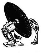
Scanned arc lamp source for mechanical TV |
The frame that holds the tubes is on an angle. That way, the tubes can pick up reflected light from the performer. The source of this light is a special type of projector. The projector contains a spinning Nipkow disc. This disc scans across a small aperture inside the projector. Lenses superimpose the image of the scanned aperture on the window. Scanned light shines though the window and reflects off the performer's face, hands and clothes. Depending on the performer's reflectivity at a particular point, more or less light bounces off. The photodiodes pick up this reflected light. The photodiode cathodes emit a weak photocurrent. Amplifiers multiply this low-level current. Transmitter. Circuits apply the amplifiers' output signal to the AM transmitter. The signal then amplitude modulates the carrier wave. The resulting radio signal propagates as sky waves. These bounce off the ionosphere and touch distant antennas. Particularly at night, homes in a large reception area can see the mechanical TV program. |