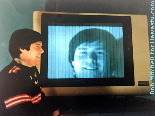
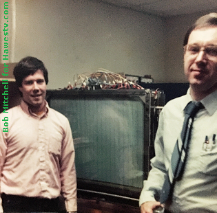
(A) Bob Mitchell & Mike DeJule with a Lucitron 34B
panel (about 1986).
This page is a memoir about Lucitron, a small R&D
company in Northbrook, IL. Lucitron pioneered flat-panel
television in the 1970s and 1980s. Panel engineer Bob Mitchell
and I contribute our memories about the company and the
panel-design process.
Bob built display tubes for Mike Dejule to evaluate.
(DeJule was the engineer who usually designed the panels. He was
also a Lucitron vice-president.) Along with his management
responsibilities, Bob personally built all the panels. That task
included these steps...
Depositing phosphor
Etching glass
Building cathodes
Degreasing
Fritting,
Assembling, etc.
Bob begins our story with an examination of panel assembly at
our Northbrook facility. (I'll join in with a few thoughts later
on.)
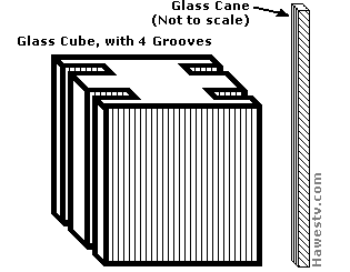
Joe Singer produced our glass cane. (Or maybe he even invented the
process.) Glass cane began with a two-inch glass cube. Bill Irvin (one of our star
machinists) would mill a groove in each side of a two-inch-square glass cube. The
result of the machining was sort of an I-shaped block. I remember Joe's
cane-pulling method, too. Joe would put the block in a special oven. This oven mounted
to a tripod-like support. The “tripod” raised the oven off the floor.
Joe heated the glass block until it melted. In the bottom of the oven was
a tiny hole. Gravity would draw the melted glass out the hole in the oven. The result
was our glass cane, with a groove down each side. The final width of each cane was
only about four tenths of an inch. Joe would cut the melted glass to the three-foot
lengths that we needed. How amazing that each glass cane was a perfect size every
time!
On track. Remember the grooves that machinist Bill Irvin milled in the
glass block? Our nichrome flat leads (electrodes) would slide into those
grooves in the glass cane: Just like a train on a track (most of the
time).
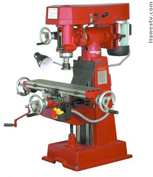
(B) Bill's vertical milling machine looked something
like this one, except it was green. (Stock photo)
(C) Bill milled two grooves in a glass cube.
Joe heated and stretched the cube into a long glass cane.
We sprayed the cane with frit.(Frit is more or less like “glass
solder.”) Then, we laid the cane out in a jig, horizontal and vertically. I
(Bob) would fire the cane.
Waffle. What came out of the oven looked like a waffle. This was the point
when we'd slide the electrodes into the cane channels. At times, this operation was a
headache. If a spot of frit was in a channel, the electrode wouldn't slide through.
Jam. If we couldn't clear the jam, we had to start over. To make
things worse, we'd have another channel right below with the same issues.
After we completed these tasks, four rows of electrode holes had to
line up.
(E) Section of electrode or “lead” (not to scale).
Lucitron technicians slid such metal electrodes into slots in the
glass cane.(4.)
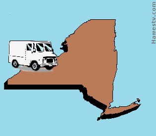
(F) Cary Stone and Bob drove a van to IBM headquarters.
(Collage, using stock photos)
First sale. We sold our first flat-panel display to IBM. Before our
model 34B, we had a different panel. The earlier panel was small. It measured roughly
eight by 10 inches. Cary Stone and I delivered it personally to IBM. There, we set
it up and demonstrated it. IBM purchased this panel for testing. But I don't think
IBM ever bought the 34B.
The panel that we delivered had 90-horizontal by 120-vertical lines. The
(photo-etched) leads came complete with each panel.
Insulators. We made our insulators out of ceramics with
the same expansion coefficient as the glass. I would spray the insulators with frit
on both sides. Then, I'd lay on leads and fire the whole piece as a sandwich. In
its time, the insulator for the 90-by-120 panel was a breakthrough of sorts. This
ceramic insulator was the largest that we could then produce.
Leads. We produced leads for the 34B panel the same way. But we had to
cut the leads to shorter lengths. Then we'd slide them into the channels in the
cane. (The insulators were 60 thousandths of an inch wide, and 20 thousandths
thick. How surprising that I still have a set of them!)
JAMES. I have a question about the smaller Lucitron tube that you and Cary Stone
took to IBM in New York State. Was this the same type as Al Hollander tried to market to
Ball and Mead?
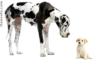
(H) Symbolic picture: The big dog stands for our
34B panel. The little dog stands for our earlier, 90 x 120
panel. Both had a distinguished pedigree! (Stock photo)
BOB. I don't think so. The goal was to make large, flat panel
tubes. The tube that we sold to IBM was proof of principle. I don't remember
going back to that size, even for color.
JAMES. Al Hollander would stop into our electronics workshop to
chat. He told me and Val Chishevsky that Mead might market a mobile display. Al
had pitched our large 34B panel, but Mead had wanted something smaller, for car
or truck use. I imagined something that might fit in a glove-box space, maybe
two units wide by one high. Al didn't tell us the details. Unfortunately,
Al never closed the deal.
BOB. We did make some small tubes for tests. The one-to-two-inch tubes
that we built for experiments were quick. A lot of times, we just epoxied them
together. Nothing like trying to frit something together and have it break, or
move out of alignment!
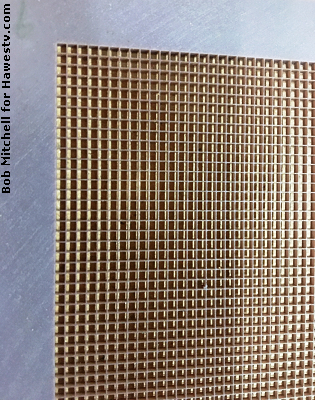
JAMES. Did you have a plan to eliminate the gaps between picture columns?
These gaps are visible in the panel photos.
BOB. Those vertical lines are a piece of cane fritted to the faceplate. The cane
was there to make a solid connection between the front and back plate. Our goal for this
connection was to prevent implosion.
In the 90-by-120 panel: I believe that I spray-fritted the ceramic plate to the
faceplate. Then I settled phosphor through the holes.
JAMES. In the lab, Schmitt and his assistant tested water samples for
transadmittance. They probably also performed other tasks, but I'm not familiar
with those. (How did you use the water in making the tubes? Was it a lubricant
during machining?)
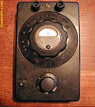
(J) The transmittance bridge that I engineered wasn't as
posh as the pictured item. Mine had a one-JFET amplifier. The output
device was an LED, instead of the meter in the photo. The JFET
operated off a 9-volt battery. (Stock photo)
Bridge. I only know about the water test because I repaired the lab's
transadmittance bridge. Our lab used this bridge to test the admittance of water
samples.
Inside the bridge were two obsolete vacuum tubes. The bridge amplifier
might have been a 37 triode. The output display was (I think) a 6E5 magic
eye. If either one had failed, I'd have had to seek a replacement at an antique
technology dealer.
Resistor. Fortunately, the problem was just a resistor that had decreased
in value. A decrease in a resistor is so rare that I saved the part! (Usually with
age, carbon resistors increase in value. Maybe this part was a metal film type. The
package was unusual.) Nobody else in the shop could fix tube technology. So I
was the elected serviceman, despite my imperfect repair skills.
Solid state.
I also designed a solid-state version of the bridge circuit for Schmitty.
Margaret Hultquist built the circuit for me. In my circuit, a 2N3819 JFET
stood in for the 37 triode. A red LED stood in for the 6E5 tube. There was a
bridge balance potentiometer, just as in the tube circuit. I don't recall the
values of my bridge resistors. Maybe I copied them from the tube circuit. A
nine-volt battery powered my model.
As far as I know, Schmitty never used my bridge. I understand. I had no
way of calibrating it. I did test my bridge, and found that it could read a
100M resistor. (I couldn't find such a resistor in our stock, so I built
it from 10M resistors.) That would translate to 1 µS transadmittance
reading (I think). The resistor represented the real part of
transadmittance, which is technically “transconductance.”
(K) Lunchroom: Off limits for eating! (Stock photo)
BOB. Nobody ate in our lunchroom. I used the lunchroom to deposit my phosphor
on the front screen glass. I used deionized water which was delivered in a tank. Or
maybe the unit took tap water and removed the minerals. If you got the chemicals in
that room in your food, they'd kill you!
BOB. I'm pretty sure that Schmitt and his assistant were working
on color TV. For a color tube, we needed to deposit each color individually.
We had to mask off the parts that we didn't want to coat. If I remember:
Each red, green, or blue strip was 60 thousandths of inch wide. We deposited
each strip between the canes we'd fritted on the faceplate.
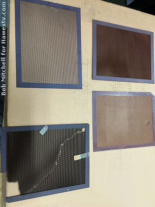
JAMES. These were handmade panels. I know that sometimes, an
imperfection would creep into a tube...
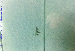
(L) Panel with hot spot (middle)
BOB. Yes. Remember, we didn't build these panels in a clean room.
Despite our best efforts, sometimes contaminants snuck into a tube. The result of
contaminants is a hot spot. The high voltage takes the path of least resistance
and starts an arc. If you look closely, you can see how the hot spot starts at
the arc and spreads outward.
I'd spend hours in a dark test room, looking for hot spots. I'd start low
with the high voltage, and slowly increase it over time. When a hot spot started,
I'd lower the HV. Then I'd leave the HV there for an hour. After that hour, I'd
increase the HV again, to see if the spot would reactivate. If the spot was bad
enough, I'd pump out the panel again. Then I'd leave the panel there for a few hours
under vacuum. Next, I'd refill the panel with Argon.
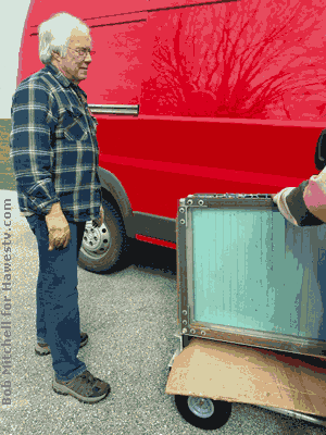
JAMES.A wistful moment (April 28, 2023): Farewell to a scrap of yesterday. This may be the last Lucitron 34B Flatscreen panel on Earth. It's the same type panel that
Lucitron shipped to the U.S. Navy, back in 1986 or so. In the photo (Left), Bob hands
over the Lucitron panel to folks who will (gently) drive it to Hilliard, OH. There,
the panel will go on display at Steve McVoy's famous Early Television Foundation Museum.
BOB. They just took the flat panel. Thanks, Steve McVoy, for saving a piece of television history.
, e-mail message to editor, May 25, 2022;
Bob Mitchell, e-mail message to editor, November 28, 2020.
▶Re: Description of Joe Singer's cane-pulling unit (glass
cane).
, e-mail message to editor, August 27, 2022.
▶Re: Electrode (lead) details, including: • Pilot hole for
pulling lead with pick. • Taper at each end of electrode. • Round
hole shape.
, e-mail message to editor, June 1, 2022;
Bob Mitchell, e-mail message to editor, November 28, 2020.
▶Re: IBM Trek, from Illinois to New York State. Cary Stone &
Bob Mitchell drove to IBM headquarters in New York to demonstrate one of
our early flat-panel displays.
, e-mail message to editor, June 19, 2022.
▶Re: Smaller Panels. Al Hollander's discussion of possible
smaller panel, with our prospect Mead Products LLC. Nothing came of
discussion.
, e-mail message to editor, April 28, 2023.
▶Re: Bob says good-bye to the panel. Helps to load it into
van for ride to Early Television Foundation Museum.
 (E) Section of electrode or “lead” (not to scale).
Lucitron technicians slid such metal electrodes into slots in the
glass cane. (
(E) Section of electrode or “lead” (not to scale).
Lucitron technicians slid such metal electrodes into slots in the
glass cane. (