Psychoacoustics: The “Tube Sound”
The “warmth” of vacuum tubes: What is it really? “Warmth” is a
psychoacoustic effect that we can hear. This article defines how an impressive tone
can come out of speakers that connect to tube hardware. Plus, how to achieve a parallel
eloquence with field-effect transistors (FETs). We don't promise to deliver the exact
same effect. Such an assertion would be sacrilege to our tube brethren. But with FETs, one
can produce a tone that is rousing, expressive, and inspirational.
Cautions and notices. A tube is a tube, and nothing else is.
For tube sound from tubes, click this link to one of
our tube
vendors. Back to the ranch: This article refers to DFETs (depletion
field-effect transistors). The DFET family includes both JFETs (junction
FETs) and depletion MOSFETs. (MOSFETs are metal oxide semiconductor
FETs).
|
Amplifier as instrument. To a hi-fi guy, an amplifier is a musical
conduit: The goal is faithful reproduction. Yet to a guitarist, an
amplifier is a musical instrument: The amplifier must reproduce the
music and evoke the tone. By “the tone,” we mean the
sensual effect of the amplification hardware.
|
|
Want to get that feelin'? Then your output transformer, capacitors,
and resistors are crucial: As crucial as your guitar body type, string
gauge, and pickup location.
The Three Sources of “Tube Sound”
|
What is tube sound? “Tube sound” comes from three sources...
- Audio transformer effects
- Amplifier design effects
- Tube effects
|
Audio transformer effects
Audio transformer sound may be the most important component of so-called
“tube sound.” The transformer launches a midrange boost, slight ringing,
and even harmonics.
Amplifier design effects
Tone. In guitar amplifiers, tone is king. A typical 1950s amplifier
chains single-ended amplifier stages together with resistors and capacitors. The nickname for
this style of amplifier is the R/C or resistance-coupled amplifier. Coupling
components add their signatures to the output signal. If the power supply is compliant, peak
signals clip or compress. The clipping is soft and clear, rather than harsh. Peak waveforms
retain round tops.
Tube effects
Even harmonics. In a classic tube amplifier, a triode provides the “sweetness”
or “warmth” of tube sound. The triode achieves this end by introducing
even harmonics.
This “tube sound” table summarizes the most important characteristics...
|
Effect Type
|
What Gets that Feelin'?
|
|
Transformer
|
- Sweetness. We also know this
characteristic as “mellowness” or “warmth.” It's
really a midrange boost. The transformer rolls off both the
highest and lowest frequencies. Reinforcing the tone, the transformer
rings slightly. The ringing may appear as even harmonics. Minimal
negative feedback reduces the ringing and broadens the bandwidth
slightly.
|
|
Amplifier Design
|
- Completeness. “Old-fashioned,” single-ended amplifiers are the
best way to achieve “completeness.” A Class-A, single-ended amplifier forms
strong, even harmonics, particularly the second harmonic. Even harmonics lend
“completeness” to the tone. The even harmonics achieve a multivocal
choir effect: Each harmonic strengthens and harmonizes with the fundamental.
- Bass response.
All R/C stages lose some of the low frequencies. But assertive bass response results from
high-impedance inputs and low-leakage capacitors.
|
|
Tube
|
- Fullness. The input impedance of a tube circuit is quite high, typically in the
hundred-thousands or millions of ohms. A high-impedance input is ultra-sensitive. It never
loads down the signal.
- Sustain (Enhanced decay time). Coupling capacitors discharge slowly into
a high impedance. The slow discharge sustains the tone.
|
Tube Effects in DFET Amps
Musicians want a semiconductor that behaves like a tube,
while producing a euphonious tone. Audio guru
Nelson Pass proves that
DFETs can do an admirable job. The table below summarizes how we produce the “tube
sound” with DFETs.
|
Effect Type
|
What Gets that Feelin'?
|
|
Transformer
|
- Sweetness (Midrange Boost) calls for a bandpass filter or an audio output
transformer. The transformer favors midrange frequencies.
|
|
Amplifier Design
|
- Completeness (Even Harmonics). With the DFET in a tube-like circuit, you'll
probably obtain even harmonics. If not, add more local negative feedback.
- Bass Response. FET amplifiers preserve bass response and bias, by stage coupling
through non-electrolytic capacitors.
|
|
DFET
|
- Fullness (Bass response) is excellent because gate impedance is
high. With a high-quality coupling capacitor, the high impedance can deliver thundering bass.
- Sustain (Enhanced decay time) follows from the high impedance input of each stage.
Low-leakage, plastic capacitors between stages prolong the tone.
- The Class-A circuit encourages even harmonics, particularly the second.
- Tube-Like Tone. Out of the box, DFETs offer
a tube-like tone: (1) Low-noise performance. (2) Overdriven DFETs distort softly,
similarly to the way that tubes do. (3) DFETs clip less than bipolar transistors
do.
|
Depletion vs. Enhancement FETs
Like a tube, a DFET is a depletion-mode device. A DFET's no-signal condition is
“partly on.” The industry is phasing out depletion FETs in
favor of more-efficient, enhancement MOSFETs (E-MOSFETs). Unlike a DFET, E-MOSFETs are
normally off. But fear not: Like DFETs, enhancement devices share the high impedance and
bass response of tubes.
Amplifier Design for DFET Amps
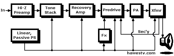
Block Diagram of R/C Guitar Amp
Standard Layout. A tube guitar amp has a standard layout. This layout produces
the desirable sonic effects that we've described. A tube-like DFET design must
also include many of the same layout features: The more, the better. These bullet
points summarize the standard layout...
- A high-gain, high-impedance preamp stage
- Inter-stage coupling only through top-quality, non-polar, plastic capacitors
(We recommend polypropylene capacitors.)
- A passive tone stack
- A recovery amplifier
- A power amplifier (single or dual-ended)
- An audio transformer
- A dynamic loud speaker
- Feedback from the speaker to the last preamplifier
- A line power supply with a rectifier, filter capacitors and maybe a choke: Sag is useful compression.
- Desirable for fidelity: A Class-A power amplifier
- Desirable for even harmonics: A single-ended power amplifier
- Optional: A pre-drive circuit
- Optional: Built-in effects circuits (fuzz, tremolo, wah, reverb, etc.)
What to avoid. Apply global negative feedback only sparingly.
(Such feedback introduces phase lag, especially with audio transformer designs. Phase lag
adds undesirable high harmonics.) No polarized or electrolytic coupling capacitors. No op amps,
Wilson current mirrors, or differential gain stages. No regulated power
supplies. No digital anything.
Enhanced Solid Tube Tech
|
How can we enhance solid tube technology? The best way would be to install exotic,
triode-like DFETs in the amplifier. At one time, such FETs were available from
Japan. We call such devices
short-channel FETs.
Nelson Pass. Solely for his own products,
Nelson Pass commissioned SemiSouth to
manufacture such FETs in
silicon carbide (SiC). Unfortunately, today SemiSouth is history. Yet SiC devices from
other foundries have reached the general market. For now, most available devices aren't
short-channel devices.
|

|
|
Ordinary DFETs have a triode region. This region is left
of the pinch-off knee. Yet this range is outside the saturation region,
where engineers operate the device in amplifiers.
One can experiment with devices in the triode (linear) region. The trick is to
reduce the source-drain voltage below the pinch-off knee. For many devices, the power voltage
would be only a few volts.
The curves (above-right) are for the naked tube or transistor. Adding a source
(cathode) resistor to the DFET linearizes the output. (1.)
|
Drain curves of hypothetical DFET. Notice flat, saturation region, right of
current knee. Left of knee is “triode” (linear) region. (Click graphic
to compare with triode curves.)
|
Straightening the curve. The source resistor improves linearity through negative
feedback: That is, using the feedback voltage to dynamically adjust the bias. Bias
adjustment also selects the drain curve. (You can see the bias voltages on the right side
of the drain curve drawings.) The device's drain curve is the device's operating path.
Using feedback bias for curve control is the same as straightening the curve, the
path. A momentary bias change causes the drain current curve to jink up or down.
Footnotes
1.
RCA, RCA Receiving Tube Manual (Harrison, NJ: RCA, 1940), 20-22.
▶Re: Negative feedback in traditional tube circuits. This material applies
equally well to FET resistance-coupled amplifiers.
|