Hawes Amplifier Archive by James T. Hawes, AA9DT
Single-Ended Guitar Amp with Dynamic Load
Pin it

• For latest revision of schematics, simultaneously key <CONTROL> and R.

Simplicity & Fidelity

Chameleon. This circuit looks like a complementary amp, but isn't! In fact, our chameleon is a single-ended (SE) amp with a dynamic load. Our amp uses two Radio Shack IRF510 MOSFETs.

Punch for Practice. This amplifier combines the simplicity and fidelity of SE design with easy-to-acquire parts. The circuit isn't particularly efficient, but it packs enough punch for a practice amp. Nelson Pass, the renowned solid-state amplifier guru, sanctions just such single-ended MOSFET designs.

No Phase Splitter. JFET Q1 is the input preamp. The JFET is a common J113, NTE457, or MPF102. (Only equivalent devices will work.) No phase splitter is necessary, because we're only driving one output device, Q3.

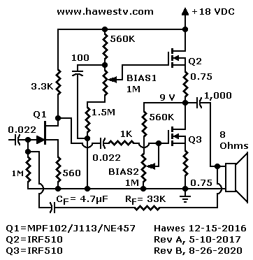
Schematic: Quasi-complementary circuit with two-FET phase splitter

Figure 1. In this single-ended circuit, JFET preamp Q1 sends the original signal to output MOSFET Q3. MOSFET Q2 is an active load and C-multiplier.

To optimize fidelity, this circuit includes source resistors at the Q2 and Q3 outputs. At the expense of gain, these resistors reduce distortion. Local negative feedback through the resistors opposes non-linear effects that arise during amplification. The circuit also includes a global feedback network, RF-CF. (1.) Consider this feedback network optional.

Dynamic load Q2 loafs along at its half-bias point. No more radiator-size drain resistors! The load gate connects to a bias network and a filter capacitor. The MOSFET amplifies the capacitor characteristic. What results is a C-multiplier that behaves like a bypassed load resistor with high stability.


DIY Considerations

Use heat sinks on the two IRF510 MOSFETs. The transistors must run cool to slightly warm. You must drive this circuit with a preamplifier (probably two JFET stages). In this design, local parts availability is a high priority. Our amplifier uses mostly Radio Shack parts. The output is typically an N- and P-channel totem pole. Instead, we use two N-MOSFETs. (Radio Shack doesn't stock the IRF510 complement, which is an IRF9510. Try Mouser.com or eBay.)

The bias adjusters are linear taper pots. Before testing the amplifier, set each pot at midrange (never at the end of its range). Test the amp under power. To bias Q2, measure volts from the 9-volt point to VCC (18V). With no signal, adjust BIAS1 for about 4.5 volts. To bias Q3, measure volts from ground to the 9-volt point. With no signal, adjust BIAS2 for about 4.5 volts.


Possible Improvements

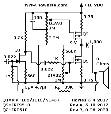
Performance. A zener diode might improve performance of the Q2 gate bias network. This zener would stiffen the regulation of the Q2 constant current source (CCS). Yet since the current source is compliant, perfect regulation is unnecessary. Those who favor a P-channel load will prefer the circuit at Figure 2. For either circuit: Experiments with the RF (global feedback resistor) value might yield improvements in gain or tone. (Not both. Larger RF for gain. Smaller RF for tone.)


Design Comments

Answers Criticisms. The single-ended design and dynamic load answer criticisms of the original two-ended design. The SE design also responds to requests for a single-ended solution without large power resistors. In our single-ended circuit, the second IRF510 MOSFET (Q2) doesn't contribute to amplification. The circuit will be less efficient than a two-ended circuit. But fidelity will likely be superior.

Schematic: Quasi-complementary circuit with two-FET phase splitter

Figure 2. Redesign of the above SE circuit with P-Channel MOSFET Q2 as a C-multiplier. Same Q1 and Q3 circuit.

Comparison to Zen Amp. Circuits similar to this one use a P-channel MOSFET for the dynamic (active) load. See Nelson Pass' impeccable Zen Amplifier circuit: An inspiration! Our IRF510 circuit is simpler than the Zen, but retains the compliant current source idea. We use a C-multiplier (Q2) instead of a zener multiplier.


Bibliography

Broskie, John. Single-Ended.” John Broskie's Guide to Tube Circuit Analysis & Design. May 18, 2014. 2016. Access on May 3, 2017. https://www.tubecad.com/2014/05/blog0290.htm ▶Re: Discussion of compliant constant current source for Zen Amplifier. Includes schematic. (Scroll quite far down, below cartoon of perplexed man.)

Houston, Mark. DIY Class-A 2SK1058 MOSFET Amplifier.” DIY Audio Projects. April 3, 2012. Access on May 5, 2017. http://diyaudioprojects.com/Solid/ZCA/ZCA.htm ▶Re: Single-ended MOSFET project without active load. Requires 40-watt, 15-Ω load resistor. Schematic include amplifier circuit and 24-VDC power supply for project. Excellent project photography. Links to other variations of project.

Loo, Heng Gin. Constant Current Source.” JK Audio Design. December 22, 2013. Access on May 11, 2017. http://jandkaudiodesign.blogspot.com/2013/12/constant-current-source.html ▶Re: Advantages of constant current sources (and sinks) in sound amplifiers. Uses tube circuits in examples: Includes CCS in preamp, SE power stage, and push-pull stage.

Meyer, Daniel. Reverb for Your Car.” Popular Electronics 25, no. 2 (1966), 50. ▶Re: The source of our optional feedback loop (CF / RF).

Pass, Nelson. Amp Camp Amp #1 - diyAudio.” DIY Audio: Projects by Fanatics, for fanatics June 20, 2012. Access on May 5, 2017. http://www.diyaudio.com/forums/diyaudio-com-articles/214808-amp-camp-amp-1-a.html ▶Re: Whole design process. 5W amp with enhancement MOSFETs.

Pass, Nelson. Single-Ended Class A.” Pass. September 1, 1998. 2016. Access on May 3, 2017. https://www.tubecad.com/2014/05/blog0290.htm ▶Re: Single-ended, Class-A amplifiers using MOSFETs.

Pass, Nelson. The SIT Nemesis by Nelson Pass.” Firstwatt.com. n.m., n.d., 2011. Access on May 11, 2017. http://www.firstwatt.com/pdf/art_sit_nemesis.pdf ▶Re: MOSFET, SE power amp with an output transformer. Two versions: Version #1 uses depletion JFETs (SJDP120R085). (These self-bias like triodes, unlike the enhancement MOSFETs that we used above.) Version #2 uses custom JFETs (Pass-SIT-1). All these FETs come from the defunct SemiSouth foundry. The semiconductor material is silicon carbide (SiC). The Version #2 JFET has characteristics that closely resemble those of a triode tube.

Pass, Nelson. Zen Amplifier.” Pass DIY. n.m., n.d., 2016. Access on May 3, 2017. https://www.passdiy.com/gallery/amplifiers/the-zen-amplifier ▶Re: Original schematic and theory of Zen Amplifier. Single-ended MOSFET design with zener multiplier (CCS) load.

SemiSouth. Normally On Trench Silicon Carbide Power JFET.” Rlocman.ru. May, n.d., 2011. Access on May 11, 2017. http://www.rlocman.ru/i/File/dat/SemiSouth/JFETs/SJDP120R085.pdf ▶Re: Datasheet for the Type SJDP120R085 power JFET. This is one of the devices that Nelson Pass uses in his SE amplifier designs. The manufacturer is SemiSouth Laboratories in Starkville, MS. Unfortunately this semiconductor foundry is out of business as of 2017. Similar devices might be available from other foundries. For example, Cree and Infineon.

Simon, Ed. A Solid State Single Ended Power Amp.” Audio Xpress.com. February 23, 2017. Access on May 10, 2017. http://www.audioxpress.com/article/a-solid-state-single-ended-power-amp •Re: Totem pole SE amplifier design: Discusses transistors vs. FETs, and includes project. Project uses bipolar transistors. Includes power supply and heat sink design.


Footnotes

1. Daniel Meyer, “Reverb for Your Car,” Popular Electronics 25, no. 2 (1966): 50. ▶Re: This article inspired our optional feedback loop (CF / RF). Thanks to World Radio History for preserving this archival copy of the groundbreaking electronics magazine. Please turn to page 50.


Go to Page:   1   2   Next

CAUTION: UNBUILT DESIGNS


Google Search
Web www.hawestv.com


WARNING. This is your project. Your achievement is entirely yours. I assume no responsibility for your success in using methods on these pages. If you fail, the same is true. I neither make nor imply any warranty. I don't guarantee the accuracy or effectiveness of these methods. Parts, skill and assembly methods vary. So will your results. Proceed at your own risk.

WARNING. Electronic projects can pose hazards. Soldering irons can burn you. Chassis paint and solder are poisons. Even with battery projects, wiring mistakes can start fires. If the schematic and description on this page baffle you, this project is too advanced. Try something else. Again, damages, injuries and errors are your responsibility.

CAUTION: UNBUILT DESIGNS. These are unbuilt designs. You might need to refine them before they'll work. The circuits show promise. My point for this page is to share some ideas that might work. If you're an experimenter, the circuits are food for thought. That's the fun of inventing. But if you need something that works the first time and works perfectly, you'd better move on! — The Webmaster


Copyright © 2017 by James T. Hawes. All rights reserved.

•URL: http://www.hawestv.com/amp_projects/amp_solid_tube/guitar-amp-single-end-mosfet.htm
Webmaster: James T. Hawes
•Revision—August, 2020
•Page design tools: HTML, Notepad & Explorer