Safety Features. Also beyond this page are safety features, such as foldback circuitry. You'll note that these are stripped-down circuits. They contain no protection against overcurrent or overvoltage operation. A short circuit in the output will quickly destroy such an amplifier. But parts are cheap and servicing is easy. If you will, build and enjoy!
|
|
|
Practice-with-Pride Amps
Rock 'n Roll Your Own! If you're both a guitar player and an experimenter, these circuits are what you need. These aren't stage amps, but they'll be just fine for a bedroom practice session. By the way, if you just want a dependable, serviceable amp, but can't play guitar, follow along. Just think of these circuits as “utility power amps.”
Must have a preamp or two. None of the circuits on this page can stand alone. Each circuit needs a power supply and a preamp or two. The preamp circuits are on our preamp page. Make sure that you add an emitter-bypass capacitor to these circuits. Use a 20 μF or larger capacitor (larger caps provide more bass). See...
http://www.hawestv.com/amp_projects/fet_preamp/fetpreamp1.htm
Battery Discharger. Don't even think of running these amps with two nine-volt batteries. If you try that, call these circuits “battery dischargers.” What? You insist on battery operation? Okay. Use hefty batteries. For example, 12 “D” cells in series.
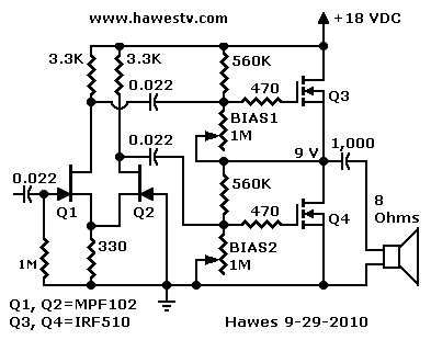
Mostly Radio Shack Parts. The first schematic is for those who seldom buy parts anywhere but Radio Shack. You can walk in the store and walk out with all the electronics that you need. For the heat sink, sorry to say, you're on your own. Find a hardware store and buy a big chunk of aluminum. Saw the aluminum chunk into two pieces. Paint the aluminum pieces flat black. The paint actually increases the magical powers of the heat sink. No kidding. Slather the transistors with silicon heat sink grease. Bolt each power MOSFET to its own piece of aluminum. Go in peace. Play loud. Sing until you steam up your bedroom or either a girl or the police show up. (If you're a girl rocker, howdy! Beg pardon. If you're a girl cop who plays rock music, cool.)
|
• NOTICE. Since I first posted this page, Radio Shack disappeared. Ah, but to quote Mark Twain, rumors of its death are greatly exaggerated. While free-standing RS stores are difficult to find, Radio Shack products sell over the Web. You'll also find a Radio Shack “store-within-a-store” at many HobbyTown locations. Check the Web for a HobbyTown with a Radio Shack Express store near you! Fate of the MPF102. Unfortunately, the revived Radio Shack doesn't sell the MPF102 JFET anymore. You'll have to buy it from another vendor ( eBay, etc.)—The Webmaster |
Most Everything from Radio Shack
|
As I Promised, the first amp is as close to a Radio Shack-only circuit as I could come. This is a quasi-complementary circuit, because Radio Shack only sells an N-channel power MOSFET. We'll use two of Radio Shack's IRF510-type MOSFETs. Fortunately, the IRF510 is an excellent device. It's exactly what we need: Rugged, sensitive and noncritical: A complete package. Needs Preamp. Again, you’d drive this circuit with a two-stage JFET preamplifier. The input capacitor should be about 0.1 uF. Phase Splitter. The two JFETs make up a differential phase splitter. I tried a one-device splitter, but it couldn't put out enough voltage to get a big swing from the output MOSFETs. The two-device phase splitter also provides needed voltage gain. The JFETs are common types, such as MPF102, 2N3819, or J113. (Only equivalent devices will work. Remember, these aren't bipolar transistors. Unlike transistor specs, the IDSS and forward drop of FETs vary.) |

In this quasi-complementary circuit, a differential phase splitter sends the original signal and its mirror to output MOSFETs Q3 and Q4. Since the MOSFETs are in series, output peaks are higher than with a single-ended circuit. |
|
Source Resistor. In the Q1-Q2 circuit, don't bypass the 330-ohm source resistor! Otherwise, the circuit won't function. Your signal must pass from Q1 to Q2 across the source resistor. If you bypass this resistor, you'll short out your signal! Use Heat Sinks on the two IRF510 MOSFETs. If the MOSFETs seem hot to the touch, then your heat sinks are inadequate. Increase the heat sink size. Paint the heat sinks flat black on both sides. (A lacquer magic marker will do just as well as paint.) Play for awhile and check your transistors again. They must operate at about room temperature: That is, cool to slightly warm. If you can cook grits on a MOSFET, you'll eat soon. But you won't play for long. |
|
Kick Up the Volume
|
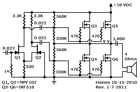
Twice the average power! This second circuit uses four drivers and doubles the average power. This quasi-complementary circuit is still not an earthshaker, but it'll definitely rattle the bedsprings. Again, most of the parts come from Radio Shack. That includes all the FETs. Use a Preamp. You’d drive this circuit with our one or two-stage JFET preamplifier. The input capacitor would be about 0.1 μF. Phase Splitter. The two-JFET phase splitter is exactly the same as in the first circuit. Match the four IRF510 MOSFETs as closely as possible. To do that, breadboard a low-current test circuit. Then Try plug in each MOSFET in sequence. Each one must put out very close to the same drain voltage. |

Here, we've paralleled a second set of IRF510 MOSFETs with the first set. By Kirchoff's Current Law, the parallel devices double the average output current. As in the first circuit, the 470-ohm gate-stop resistors discourage racing and VHF oscillations. The resistors are crucial. Oscillations could destroy the drivers. |
|
Use Heat Sinks on the four MOSFETs. You might need to adjust the value of the 330K bias resistors. Pots aren't okay, because each one would adjust two parallel devices. If the two devices vary from one another, you still won't achieve the ideal bias voltage! |
|
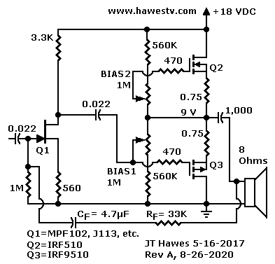
By Popular Demand!True Complementary CircuitUses Complement to IRF510. Amp builders have asked for a true complementary version of the first amplifier above. Others have requested negative feedback for improved fidelity. The new circuit achieves both goals: (1) The bottom power amplifier stage Q3 is an IRF9510, P-channel MOSFET. This is the P-complement of the IRF510 at stage Q2. (2) There are two types of feedback in this revised circuit: First, you'll notice degenerative source resistors on each of the three FETs. Second, you'll notice a feedback loop between the speaker coupling capacitor and the gate of JFET Q1. This optional feedback loop is similar to what many tube guitar amps use. |

Upgrade to the first schematic above. For builders who can find the complementary MOSFET IRF9510, which is a P-channel device. This circuit should give better fidelity than will the other circuits. The feedback loop through Resistor RF is optional. This loop should improve fidelity. (1.) |
Gain vs. tone. For more gain, increase the size of the resistor RF. For better tone, decrease the size of the same resistor.
Simpler design. Without the need for phase reversal in the preamplifier, the new circuit eliminates one JFET. (You may still use differential JFETs if you please. Just connect the 4.7µF feedback capacitor CF to the non-inverting input.)
Heat Sink Requirement. For the heat sink, follow the suggestions for the other circuits above.
More to come!
Footnotes
1. Daniel Meyer, “Reverb for Your Car,” Popular Electronics 25, no. 2 (1966): 50. ▶Re: This article inspired our optional feedback loop (CF / RF). Thanks to World Radio History for preserving this archival copy of the groundbreaking electronics magazine. Please turn to page 50.
