
|
Who is watching you?
As you watch TV, could TV be looking back? In his book 1984, George Orwell predicted that our TV sets might also watch us. For the uninitiated, that claim once seemed like fiction. Today with set-top boxes, television watches us in a limited way. But what if living room TV always had two-way capabilities, and we just didn't know? Well, that's almost true. If we add a few parts to a standard TV set, it can indeed reproduce anything in front of it.
|
|
|
Von Ardenne's TV Looks Back
Manfred von Ardenne patented an electronic flying spot scanner (FSS) in 1931. Like TV cameras, flying spot scanners dissect a three-dimensional image. Each device outputs a series of one-dimensional values. The difference lies in how the two devices scan. Most video cameras form an internal, electron image and scan that image electronically. A flying spot scanner uses light to dissect an external image.
The first cloud of von Ardenne's thunderous brainstorm is this discovery: As we view TV pictures, the TV actually scans us! Von Ardenne's scanner is a TV monitor with a blank raster (gray picture). Lenses focus the raster on the subject. A phototube bank picks up the raster as it reflects off the subject. The reflected raster retains all the subject's shadow detail. That is, the phototube output is a video image of anyone in front of the TV! TV is watching the viewer.
Televerter
|
Flash forward to 1964. That was the year when Melvin Shadbolt, W0KYQ invented Televerter, a legend in homemade electronics. Televerter is a monochrome flying spot scanner, but without the dedicated CRT. Shadbolt founded an Amateur video supplier that he named ATV Research. Through the 1960s and 1970s, Mel sold Televerter assembly manuals and parts to radio amateurs. Some of Mel's other products included television camera kits, RF modulators and closed-circuit TV equipment. The company still exists, and it still sells video equipment. Unfortunately, it no longer markets Televerter plans and camera kits. |
Vanishing CRT. I mentioned that the Televerter doesn't have a CRT. How does Mel get along without it? Simple. A second TV set is Mel's rasterizing scanner! Sheer genius. Mel's method cuts the usual flying spot scanner circuitry in half. Removing the CRT and support electronics also reduces the circuit size tremendously. Mel's marvel would about fit into a shoebox. That's enough room to hold five tubes, several controls and the lens. Of course, for the power supply, Mel's gadget still requires a second chassis.
The Televerter outputs are 300-ohm scanner RF, and 75-ohm output monitor video. Typical controls adjust the oscillators and switch the video phase, etc. Inside the device are...
| • Two sync oscillators | • An RF oscillator | • A video pickup |
| • A video amplifier | • Slide projector-type optics | • 7 Controls |
That's all, folks! Notice what the circuit doesn't have: There are no sweep circuits, no deflection amplifiers, and no high voltage power supply. Again, there is no CRT. The circuit neither contains nor needs a flyback transformer. There is no yoke. The sound system is whatever you already have.
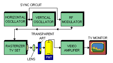
Televerter block diagram
Here's how Mel's gadget works: The sync circuit and RF modulator produce a raster on a small TV. A condenser lens focuses the raster on a 35mm slide. Line by line, the TV's raster shines through and thereby scans the transparency. The varying density of the transparency causes raster brightness to vary proportionately. A type 931A photomultiplier tube (PMT) varies its output signal in step with brightness changes. Amplification inside the PMT multiplies the video signal by tens of thousands of times.
Video Amplifier. Next, the five-stage video amplifier further strengthens the signal. Special equalizing networks peak both the high and low frequencies. The amplifier includes a switchable phase inverter. The last stage matches the output to a 70-ohm, coaxial cable. The cable connects to the monitor's video input. Of course, the sync also couples to the video amplifier. During blanking, the sync switches off the picture signal.
RF Modulator. Then the output signal modulates a carrier wave, for TV channel 3. The carrier originates in a one-tube transmitter (the RF modulator). This circuit outputs a TV signal that any home TV can reproduce.
Using Televerter. You sync the rasterizing TV and display monitor to Televerter. You insert a transparency into Televerter's slide holder. Then you focus the raster from the small monitor on your transparency. Proper focus involves both positioning Televerter and focusing the Televerter lens. Televerter's amplified pickup sends the rasterized image to the display video monitor. For best picture, you should tweak the scanning TV controls and the Televerter controls...
Televerter Controls
| • Video (PMT) Gain Pot | • Phosphor Delay Pot | • HF Peak Trimmer Cap | • Video Phase Switch |
| • Horizontal Frequency Pot | • Vertical Tilt Pot | • Vertical Frequency Pot | • Objective Lens Focus Adj |
Color Model. Mel also invented a color flying-spot scanner. Interestingly, this version preceded the black-and-white Televerter that I've described. The color scanner uses three PMTs. Two of these are 931As. The third PMT is an IP21, and it picks up the blue signal. Because this scanner includes a dedicated CRT, we can't really call the scanner a Televerter. For the CRT, Mel used a serviceman's substitution picture tube. This monochrome tube, a type 5AXP4, measures five-inches diagonally. Two salvaged TV chassis provided many of the circuits: One chassis became the flying spot scanner. Mel converted the other chassis into his sync and blanking generator. The color electronics produce NTSC-compliant I, Q, burst and luminance signals. Mel's story about the color scanner appears in QST for September, 1960. Unfortunately the text doesn't provide schematic diagrams.
Monochrome Televerter Tube Complement
| Tube | PMT | Video Amp #1 | Video Amp #2 | Video Amp #3 | Video Amp #4 | Video Amp #5 | Blocking Oscillator | Blocking Oscillator | Keyed Hartley Oscillator |
| Function | Video Pickup | Preamp | Phase Switch | Sync / Video Mixer | Preamp | 70Ω Matcher | Horizontal Sync Generator | Vertical Sync Generator | RF Modulator |
| Type | 931A: 9 Dynodes | 1/2 6AN8: Pentode | 1/2 6AN8: Triode | 1/2 6Q8A: Pentode | 1/2 6Q8A: Triode | 1/2 12AT7: Triode | 1/2 12AU7: Triode | 1/2 12AU7: Triode | 1/2 12AT7: Triode |
Go to Page: 1 2 Next