|
|
|
- Duplicate your LED driver circuit (power amplifier) once for two-color TV. For three-color TV, make two copies of your LED driver.
- Connect the LEDs to the new LED drivers.
- Test the set.
Option: Derived Color (D/C)
Following the instructions above, build a two-color camera and a three-color monitor. You can build your camera to pick up any two of the additive primary colors. Just install the proper color filters over the phototransistors or photodiodes. With a matrix circuit and an inverter, you will derive the third color. The trick? You might not have the third color, but you can create its complement. A bit of electronics turns the complement back into the "missing" primary color.
- Derive Blue... You want a blue signal, but your camera only picks up green and red.
- At the monitor, connect a potentiometer to the red and green LED driver outputs. This potentiometer is your resistor matrix. Some point on the pot's resistance element corresponds to yellow, the complement of blue.
- With a transistor, invert the yellow signal, and you have your blue. The result is as accurate as if it came from a blue phototransistor.
- You can derive this third color signal at the camera or at the monitor. For maximum savings in circuitry, derive the signal at the monitor (LED driver).
- Derive Green... Suppose that you only have red and blue, but want green.
- Connect a potentiometer between the red and blue transistor collectors (or op amp outputs).
- The red signal is at one end of the potentiometer. The blue signal is at the other end. With the wiper at the center position, you get a mix of red and blue, or magenta. This magenta signal is what you want. Center the wiper.
- Run the wiper of the pot to the base of a new transistor (or an op amp input). With the transistor or op amp, invert the magenta signal. The inverted signal is your green drive signal.
- Derive Red... Now you want red, but only have green and blue. Cyan is between green and blue. With a transistor, invert the cyan signal and you have your red.
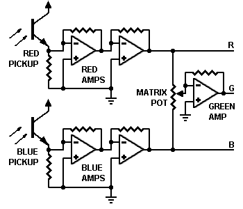
Another way to derive a third color: An inverting mixer.
Inverting mixer. An inverting mixer is an easy way to derive a third color. (See the schematics above.) For experimental use, use the circuits as-is. The phasing is only approximate. For better phasing, add level-adjustment pots to the transistor inputs.
- Red. To derive the red signal, use the left circuit.
- Green. To derive the green signal, use the middle circuit.
- Blue. To derive the blue signal, use the right circuit.
Theory. Each transistor is an inverting phase-splitter. After a 180-degree phase shift, the input signals mix at the common collector resistor. Neither amplifier has any voltage gain. Yet each amplifier offers an 11.8-times power gain. You can take the in-phase signal off the emitter of each transistor. The emitter signal includes the power gain.
Option: Pseudocolor (P/C)
The simplest pseudocolor system outputs two colors. This method requires no quantizing and no digital circuits. A two-ended analog amplifier will serve excellently. You can achieve very effective pseudocolors by applying the monochrome signal to the inputs of a difference amplifier. The inverted signal then drives one color output. The non-inverted signal drives the other color output.
In the nearby schematic, the collector of transistor Q1 provides the inverted or orange signal. The cyan, non-inverted signal appears on the collector of transistor Q2. The two collector signals are 180 degrees out of phase with one another.
The output resistors may be fixed or variable. Using variable resistors and a maximum signal, you can adjust the white balance. When the output appears white, you've achieved balance.
If you desire a third color, it could be the midrange or difference signal between the two output signals. (For example, the midpoint of a 50K pot VRZ that connects between the Q1 and Q2 collectors.) The third signal is 90 degrees out of phase with each of the other two signals. If VRZ is smaller than 33K, it introduces crosstalk between the Q1 and Q2 outputs. The crosstalk alters the phase relationship of the three signals.(This is how a matrix in a color TV works.)
Amplifier. In most cases, the third color requires its own amplifier after VRZ.
Go to Page: 1 2 Back
Article directory
- Continuous vs. Sequential
- Continuous Method
- Two-color
- Discrete three-color
- Derived three-color
- Pseudocolor
- The Camera
- Two-color table
- The Monitor
- Color balance
- Option: Derived color (D/C)
- D/C Schematic
- Option: Pseudocolor (P/C)
- P/C Schematic
- Google search