
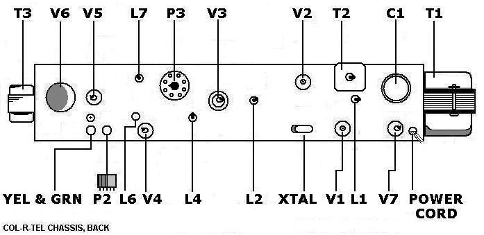
Col-R-Tel chassis, back, top-left to right
| Part ID | Part # | Name on panel | Function | Value | Comment |
| T3 | 1048 | NA | Motor transformer | Unknown | Transformer with paper bells. Motor brake. |
| V6 | NA | NA | Motor speed control | 6BL7 | Octal tube. Motor speed control amplifier. |
| V5 | NA | NA | Video output amplifier & motor speed control | 12BH7 | 9-pin miniature tube. Motor control error amplifier. Other half of tube is color video output amplifier. |
| L7 | 1076 | 6.8-33 μH, est. | Top row: Coil with adjustment slug. Tunable 3.58-MHz trap. Note: Only on Model 100-2. On Model 100-1, adjustable trimmer cap C20 occupies same chassis hole. C20 would be in series with fixed choke L5. | ||
| P3 | 1016 | Phenolic | Top row: Octal socket for connection to disc commutator & drive motor. | ||
| V3 | NA | NA | Phase switcher | 6BC7 | 9-pin miniature, phase switcher (in shield). Triple diode. |
| V2 | NA | NA | Subcarrier amp | 6U8 | Top row: 9-pin miniature, subcarrier amp. Half of tube is crystal ringing amplifier. Other half of tube is phasing coil driver. |
| T2 | 1054 | 22-56 μH, est. | Top row: Can transformer with adjustment slug. 3.58 MHz, burst transformer. Has two tuning slugs. Adjust primary of T2 through hole in rear panel. Adjust secondary (bottom of T2) through hole in front panel. | ||
| C1 | 1050-2 | Four-section filter capacitor (A-B-C-D) in can. |
C1-a,b,c,d (top row).
|
||
| T1 | 1049 | 120VAC primary; 300VAC secondary | Power transformer |
Col-R-Tel chassis, back, bottom-left to right
| Part ID | Part # | Name on panel | Function | Value | Comment |
| Yellow & green wires | H | NA | Wires from converter box to TV | Length 18" | Yellow: CRT cathode connection; Green: CRT grid connection |
| P2 | 1084 | NA | Cable from converter box to TV | Length 18" | Bottom row-left: 5-pin, phenolic plug (male) with orange & blue wires. (Same connector as on huge, multi-cell combined A & B batteries in old, luggable tube radios.) |
| L6 | 1001 | Chroma bandpass tuning on first 6BE6 grid | 90 μH | Bottom row-right: Coil with adjustment slug. | |
| V4 | NA | NA | Demod | 6BE6 | Bottom row: 7-pin miniature, pentagrid converter |
| L4 | 1076 | Demod input bandpass tuning of phase-delayed, 3.58 CW | 15-39 μH, est. | Coil with adjustment slug | |
| L2 | 1078 | 15-39 μH, est. | Phase coil with adjustment slug (Phasing Coil) | ||
| Xtal | 1032 | 3.58 MHz | Bottom row: Color crystal | ||
| V1 | NA | NA | Burst amp | 6U8 | Bottom row: 9-pin miniature tube. Half of tube is burst keyer. Other half is burst amplifier. |
| L1 | 1076 | 15-39 μH, est. | Variable choke for burst input tuning. Just above and between V1 and V7. | ||
| V7 | NA | NA | Power rectifier | 6X4 | 7-pin miniature, power rectifier (bottom row) |
| Power Cord | NA | NA | Power cord | Length 9 ft. 6" | To 117VAC main |
Col-R-Tel Wires & Cables
| Part ID | Part # | Function | Length |
| P1 | Kit Part D | Kit cable for installation on TV. Has five-pin, female connector. Plugs into P2 on converter box. Blue: Vertical sync. Orange: Horizontal sync. Black: TV chassis ground. | 18 inches |
| P2 | NA (part of converter box) | Converter box cable. Has five-pin, male connector. Plugs into P1 from TV (kit cable). Blue: Vertical sync. Orange: Horizontal sync. Black: TV chassis ground. | 18 inches |
| Wires & connectors | NA | Converter box wires with connectors. Yellow: CRT cathode connection. Green: CRT control grid connection. | 18 inches |
| Wires & connectors | Kit Part H | Kit wires (from TV) with connectors. Yellow: CRT cathode connection. Green: CRT control grid connection. | 18 inches |
| P4 / P5 | NA | The P4 / P5, removable cable that plugs between P3 & P6 (kit cable with 2 connectors). Carries commutator data to select reference & control motor speed. | 4 feet, 6 inches |
| P6 | NA | Wires from color wheel commutator to P6 | 8 inches |
| Cord | NA | Power cord | 9 feet, 6 inches |
| Size Control Wire | NA | Red wire: Solder to high-potential side of horizontal yoke coil | 18 inches |
| Size Control Wire | NA | Black wire: Solder to low-potential side of horizontal yoke coil | 18 inches |
| Size Control Wire | NA | Green wire: Solder to either side of vertical yoke coil | 18 inches |
| Size Control Wire | NA | Yellow wire: Solder to either side of vertical yoke coil | 18 inches |
Go to Page: 1 2 3 Back