Question. What talks like Andy Griffith, spins like a flying saucer, and smells like hot rosin?
Answer. Colordaptor, a gadget that people once installed on
black and white TV sets. The TV could then receive and reproduce color pictures. Of course,
the transmission had to be in color.
Colordaptor is a hybrid. It combines the 1951 CBS system and our 1953, US television system NTSC...
- From the CBS system, Colordaptor inherits the color wheel. The wheel paints hues over the picture.
- From NTSC, Colordaptor inherits color-decoding electronics.
- Uniquely, Colordaptor introduces electronics that convert NTSC color to field-sequential color. The most
distinctive part of the unique electronics is the "tritch." The tritch is a tristable, electronic multivibrator that
sequentially switches between R, B and G reference signals.
Colordaptor was a homemade system, rather than a kit or a production appliance. People built the
unit from instructions in a 1956 Radio Electronics article. No two Colordaptor systems are
alike. For this reason, restoring 1950s Colordaptor technology is particularly challenging.
Cliff Benham's hobby is field-sequential, mechanical color video systems. He's refurbished
both Col-R-Tel and Colordaptor systems. Cliff has also designed and demonstrated his own color wheel systems.
I recently interviewed Cliff about his restoration of a Colordaptor system. (I've edited Cliff's comments.)
Jim: How did you find the Colordaptor, and what was its condition?
Cliff: In February 2007, a generous friend lent me the Colordaptor unit. He did so because
I wanted to learn about it by working on it. Until then, I'd only worked on Col-R-Tel units. I
offered to restore the Colordaptor.
The Colordaptor
is a complete, hand-wired unit on an salvaged amplifier chassis. The circuit is the entire device, just as in the
article. When my friend gave me the unit, it was about 15 years old. The Colordaptor seemed to be untested.
I thought that it probably needed an alignment. I wanted to connect this unit to a TV set for the first time. I
wanted to see what Colordaptor could do. Yet at first, just making it operate caused me some difficulty.
Inside the Colordaptor, I found low-voltage trimmer caps for use with solid-state circuitry. With 200 volts
across these capacitors, some of them shorted.
I spent time learning and testing each part of the circuit. Before I could hook the
Colordaptor to the TV, I had to test the Colordaptor alone. Afterward, I started aligning
Colordaptor to see if I could make it work.
Jim: Your Colordaptor description sounds as if you rebuilt the entire
circuit.
Cliff: I rebuilt some parts, but others were okay. See the pictures.
Jim: The old PC board that I see must be an original terminal board,
as in the Colordaptor article.
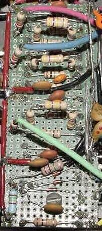
Cliff: It is actually a piece of green fiberglass Vectorboard with 0.1-inch
spaced holes.
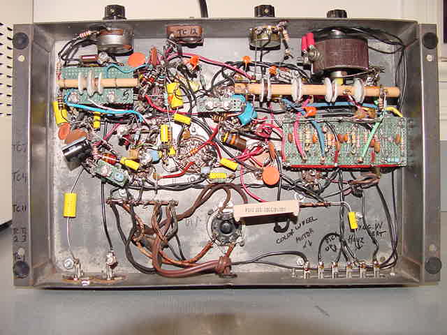 Under the Colordaptor chassis
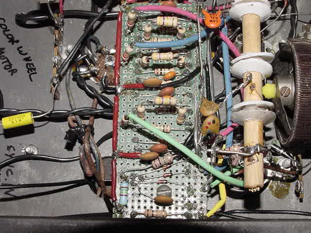 Chassis detail: Left: I/O. Middle: Tritch circuit. Right: (Bottom to top) R, B & G coils on common core.
Far right: Motor speed rheostat.
Chassis detail: Left: I/O. Middle: Tritch circuit. Right: (Bottom to top) R, B & G coils on common core.
Far right: Motor speed rheostat.