Color Wheel Starts Rolling
It's June 1951, and color TV is here! Everybody wants it, but few can afford it. Then ingenuity comes to the rescue. Equipped with an electronics magazine, a soldering iron and that old seven-inch black-and-white TV set, you homebrew your own color TV. Riffling through the well-stocked junkbox, you probably find all the necessary electronic parts...
- Two resistors
- Two potentiometers
- A four, five or six-pole switch (depending on your TV model)
|
|
|

Typical wiring changes. Some sets require more poles on the switch.
New Frequencies
The basics. All TV sets have timebases. Inside each TV timebase is a horizontal and a vertical oscillator. These oscillators output frequencies that control picture scanning. Picture scanning is what forms pictures on the screen. In the CBS color system, both oscillators operate at higher frequencies than in the regular American TV system (NTSC).
CBS frequencies. For the horizontal frequency, the CBS system uses 29,160 instead of 15,750 Hz. For the vertical frequency, the CBS system uses 144 instead of 60 Hz. Fixed resistors in series with the TV's front-panel “hold” controls set these timebase frequencies. You'll add a multipoint switch that selects the monochrome or color frequency. The switch connects either the old horizontal and vertical resistors or new ones. The resistors that you need to add are all fixed resistors. The new parts connect in series with the horizontal and vertical hold potentiometers. A typical value for the new resistors is 20K. In some models, a 10K resistor does the trick.
Extra size controls. The switch also selects a second horizontal width and vertical height potentiometer. These parts are identical to those in a stock set. The new pots keep the color picture the same size as the monochrome picture. These pots are definitely worthwhile! Without them, whenever you switch to color, you must increase picture size. All the size adjustments could get to be a major pain in the neck. With the second set of pots, you adjust the color picture size just once. And then you're done.
Circuit Details
The table below summarizes the wiring changes for several popular TV models. The changes allow your set's horizontal and vertical oscillators to operate at higher frequencies. If you know your thumb from a soldering iron, you can't go wrong. Peter Goldmark and his CBS engineers worked everything out.
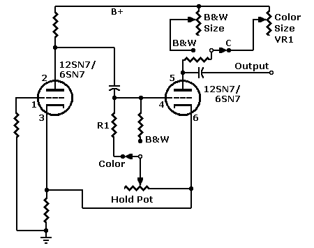
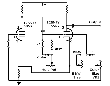
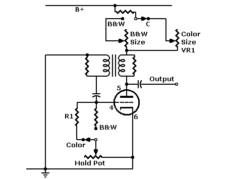
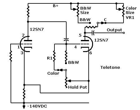
About the table. The table below lists five TVs with similar circuits. All these sets use a 12SN7 or 6SN7 tube for the horizontal and vertical oscillator. Another common point among the sets is that they use electrostatic deflection. The sets also have scope-like power supplies. That is, the high voltage doesn't derive from a flyback power source. The added fixed resistors control oscillator frequencies. Each resistor usually runs between ground and the grid of a triode. The triode could be part of a multivibrator. Or it could be a blocking oscillator. In the table, the (B&W) value indicates the stock resistor in the monochrome circuit. The (C) value is the resistor value that you must add.
Circuits Allow Conversion to CBS Color Standard |
|||||||
| TV Model | Horizontal hold resistor, R1 | Vertical hold resistor, R1 |
Add: Horizontal width pot VR1 |
Add: Vertical height pot VR1 |
V & H tubes | Switch | See Schematic |
| Switch Pole | 1 | 2 | 3 - 4 | 4 - 6 | NA | NA | NA |
| Admiral 24D1-E1-F1-G1 | 270K(B&W) → 20K(C) | 560K(B&W) → 20K(C) | 2.5M | 2.5M |
V: 12SN7 H: 12SN7 |
5PDT | #1 |
| Belmont 22A21, 22AX21, 22AX22 | 22K(B&W) → 2K(C) | 220K(B&W) → 10K(C) | 500K | 2M |
V: 6SN7 H: 6SN7 |
5PDT |
H: #1 V: #2 |
| Hallicrafters T54 | 270K(B&W) → 20K(C) | 560K(B&W) → 20K(C) | 2.5M | 2M |
V: 12SN7 H: 12SN7 |
6PDT |
H: #4 V: #2 |
| Motorola H71 | 22K(B&W) → 2K(C) | 470K(B&W) → 20K(C) | 20K | 5M |
V: 12SN7 H: 12SN7 |
4PDT |
H: #3 V: #1 |
| Teletone TV149 | 220K(B&W) → 10K(C) | 470K(B&W) → 10K(C) | 5M | 10M |
V: 12SN7 H: 12SN7 |
4PDT | #5 |
Generic schematics. Below the table are five generic schematics. Many seven-inch TV sets of the late Forties and early Fifties use circuits very close to these. You'll find such circuits in both the horizontal (H) and vertical (V) deflection timebases. Of course, exact wiring tends to differ slightly between models. Use our schematics for a guide, but always refer to your set's exact schematic.
RCA horizontal circuits are a marked departure from these schematics. In its seven-inch sets, RCA adopted automatic phase correction for horizontal oscillators. Converting such sets for the CBS system requires switchable modifications to the AFC circuit. You need at least a six-pole switch. Regardless of manufacturer, typical sets with larger picture tubes use automatic phase-correction circuits. For conversion, the two most likely RCA candidates are models 630TS and 8TS 30.
♦ WARNING: Before modifying your set. Keep safe! Know what you're getting into and why. Before proceeding with changes, read our disclaimer. (At the bottom of this page, see WARNING.) Word to the wise: Without extra equipment, these changes won't allow you to receive color broadcasts on today's TV sets.
Automatic Size Control
The extra size controls certainly add complexity and tedium to the conversion process. If only the TV could adjust its own size! Actually, an automatic size control circuit might be possible.
Circuit description. Imagine a limiting amplifier with an adjustable output. You'd insert this amplifier between the sync multivibrator and the sweep capacitor. The limiter amplifies, inverts and clips sync pulses. Regardless of input frequency (NTSC or CBS), the limiter outputs pulses of the same height. Since the limiter inverts, you'd connect it to the negative sync side of a multivibrator. A blocking oscillator circuit would probably require an extra inverter stage.
"Bare-bones" automatic size control. A passive automatic size control might be possible. The passive circuit wouldn't invert. It would connect between the sync oscillator and the sweep capacitor. The bare-bones size control consists of a diode and a resistor. You determine resistor value by experimentation. The resistor sets the diode's clip voltage. Instead of a fixed resistor, you might prefer a calibration pot. You'd only need to set this pot once. Unlike the duplicate size controls, this pot would mount right at the circuit.
Setup. Here's a rough idea of how to adjust the new automatic size control...
- Switch the H and V multivibrators to the "CBS" position.
- Switch on TV power.
- Set the original size controls for the CBS system.
- Switch off TV power.
- Connect the automatic size controls.
- Switch on TV power.
- Set the automatic size controls for the best picture.
- Switch off TV power.
- Switch the H and V multivibrators to the "NTSC" position.
- Switch on TV power.
- Check to see that the picture remains the right size.
|
Click and go... AdmiralBelmont Hallicrafters Motorola National Radio Philco RCA Teletone |


