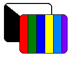
About TV Delay LinesA basic television picture has two layers:
|
|
Why a delay line? A delay line keeps the faster, luminance image in step with the slower, chrominance image. The narrowband chrominance signal requires more processing than the wideband luminance signal. This processing takes a brief, but significant time. The delay line assures that the two images start scanning across your screen at the same time. Without the delay line, you might notice that the monochrome picture starts before the color overlay does.
|
|
|
Wind Your Delay Line
Winding Tips
Not hand-wound. A delay line isn't a hand-wound coil. This job requires a lathe, or some suitable coil-winding jig. Coil winders are available on Amazon.com.
For information on homemade coil winding machines, click...
Time vs. turns. Our final coil delays the luminance by about 1.3 μS. Your results might vary. For an exact delay, you must trim the coil. Delay time is proportional to the number of turns. Yet the coil isn't a pure inductance. The number of turns changes both the coil inductance and distributed capacitance. The trimming procedure appears later in this article.
|
Disclaimer. This is your project, and the benefits accrue only to you. On the other hand, all risks of this project are also yours. The author takes no responsibility for your results. The author takes no responsibility for any damage or injury that you might sustain. This project includes the usual hazards. Use common sense. Don't connect anything to a television set. Don't drop power transformers on your toe. Don't pick up your soldering iron by the hot end. If you don't know anything about electricity, leave it at the wall outlet. |
Construction Procedure
Original art by James T. Hawes
- Cut a 23-inch piece of RG-59U coaxial cable.
- Pull the center wire lead and its polyethylene sheath from the cable. Leave only the metal braid and its plastic cover.
- These pieces serve as a form for your delay line coil. Temporarily slip them over a metal rod. During winding, the rod stiffens and supports the cable.
- For the winding, use # 36, enameled wire. Apply coil windings with a lathe. Wind the # 36 wire around the coaxial cable for a length of 22 inches, at 128 turns per inch. The approximate number of turns is 2,816.
- Connect leads to opposite sides of the winding.
- Cover the winding with a very thin dielectric paper. You'll find such paper inside old capacitors. Pull out the paper and reuse it.
- Cover the dielectric paper with tin foil. The foil must extend past the end of the paper. Make sure that the foil doesn't touch the winding.
- Ground the tin foil to the inside braid. Be careful not to short the winding to the grounding foil.
- Remove the metal rod.
- Cover the entire winding with electrical tape.
Trim your Delay Line
- Terminate your delay line. Connect a 1,000-ohm resistor to each end of the signal line. The other end of the resistor goes to signal ground.
- Watch the color picture.
- Do the color and monochrome images superimpose, with no color outlines
on either side of the image?
- Yes: Stop. You're done!
- No: Proceed with the next step.
- Do you see color outlines on the left side of the black-and-white
picture? (This is the most common situation.)
- Yes: The delay line is too long. Proceed with the next steps.
- No: Skip to step 6.
- Remove a few turns from the delay line.
- Recheck image superimposition. Do the monochrome and color images
match?
- Yes: Stop. You're done!
- No. I still see color outlines on the left: Repeat steps 4 and 5.
- No. I see color outlines on the right: Perform steps 7 and 8.
- Do you see a color outline to the right of the black-and-white picture? Yes: The delay line is too short. Proceed with the next steps.
- Add a few turns to the coil.
- Recheck image superimposition. Do the monochrome and color images
match?
- Yes: Stop. You're done!
- No. I still see color outlines on the right: Repeat steps 7 and 8.
- No. I see color outlines on the left: Perform steps 4 and 5.
Variations
Circuit design by James T. Hawes
Modular Construction. A 23-inch piece of coax makes a long, floppy and unwieldy coil form. This form won't fit any conventional hand winding jig. An easier way to complete the winding might be to break it into modules. Cascading delay lines is perfectly all right. A builder could then wind a 22-inch delay line in say, four sections.
Each modular winding would be 5.5 inches long. The winding would have 704 turns of wire. Each coil form (length of coax) would be some 6.5 inches long. The extra inch in length prevents the winding from extending to the end of the form.
Connect the ends of the form modules together. Terminate the first and last form module with a 1,000-ohm resistor.
Making a winder. A homemade coil winder might adapt fairly well to making modular delay lines. I have some ideas on how to proceed. In a typical winding machine, a crank turns a central rod. Hardware stores carry suitable rod stock. Posts with bearings support the rod. Two cone-shaped mandrels clamp to the rod. The rod them becomes an axle to turn the two mandrels. These mandrels hold the coil form. A mechanism applies friction to the axle. This friction prevents unwinding and backlash.
Look, ma! No mandrels! To wind a coil on a small coax form, slide the form over the rod. If the coax is fairly tight, you need no mandrels. If the coax is loose, you might secure it with a couple of wire ties. When the winding is done, you cut the ties and remove the coil.
|
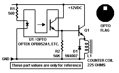
Turn counter. Making a 704-turn coil is still no picnic. I recommend a turn counter circuit. You could trigger an electromechanical counter with an opto interrupter or Hall sensor. The interrupter circuit could drive an emitter follower. The follower (Q1, right) would develop enough current to operate a counter. Some counters require a Darlington follower, such as a TIP120. The Darlington outputs enough power to drive a fairly inefficient counter. Use a heat sink on the Darlington. |
|
About the wire gauge. Number 36 wire is mighty small. Some type of feed system seems like a good idea. Otherwise, maybe someone will try to wind a delay line with # 30 gauge wire instead. The coil would be longer, and the distributed capacitance would be greater. I don't know the difference in inductance per turn of wire. I do know that # 30 is easier to work with than smaller gauges are. Maybe one of you experimenters will provide the missing data on # 30 wire. Please!