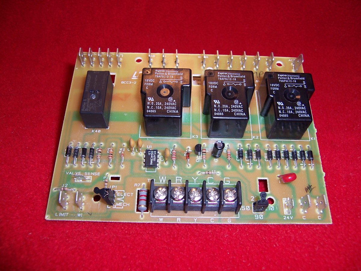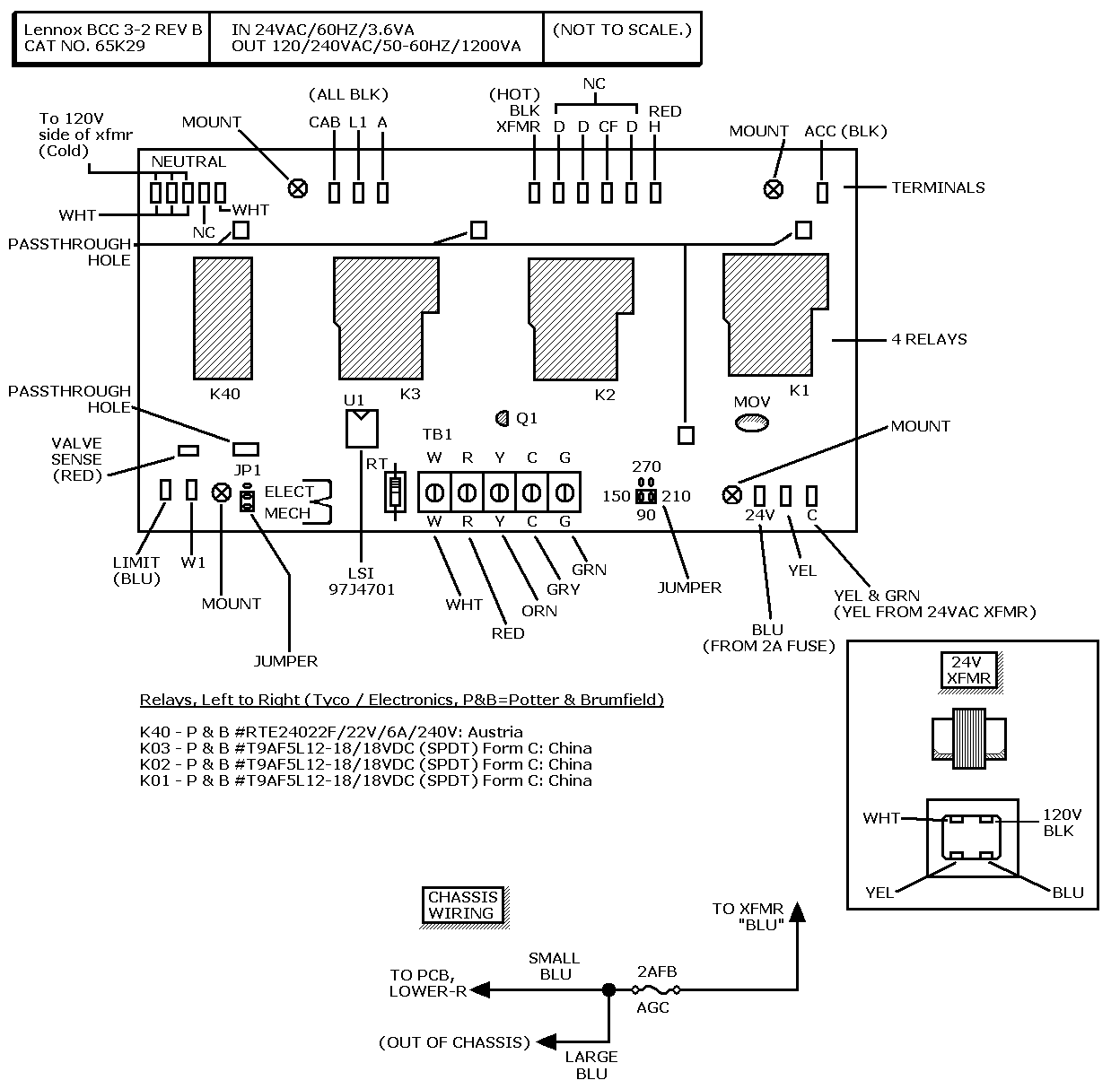
Above: Board layout, with wire colors from our installation.
120-Volt Section
Spade Terminals, Left to Right
- Neutral terminals: The board has five.
- CAB Terminal. At the "CAB" terminal, line voltage enters
the board.
- L1 Terminal. 120VAC line voltage input. (Unused on our system.)
- A Terminal. Blower speed terminal for active cooling.
- XFMR Terminal. The "XFMR" terminal sends 120VAC to the damper
motor or combustion motor and transformer.
- D terminals. The board has three dummy "D" (unconnected) terminals.
- CF Terminal. Continuous fan terminal.
- H Terminal. Blower speed terminal for heating.
- ACC Terminal. A terminal for accessories, such as an electronic air cleaner.
- HSI Terminal. Not for use on this model.
Blower Speed Taps. Notice the speed taps at the upper right corner
of the BCC board. Make blower speed tap changes here. Secure unused speed taps to the dummy "D" terminals.
Connect the active heating tap to Terminal H. Connect the active cooling tap to Terminal A.
To Change a Speed Tap, turn off power. Remove the existing
speed tap from Terminal H. Place the tap on a "D" terminal. Select a new speed wire. Place it on
Terminal H. Restore power. Blower speed tap information appears on the G20 unit wiring diagram.
24-Volt Section
Terminals, Left to Right
- Safety Circuit Terminals.
- Thermostat Jumper. Set the jumper for your thermostat type, Elec (electronic) or Mech
(electromechanical).
- Thermostat Screw Terminals W, R, Y, C, and G. Typically, the letters apply to wire colors.
W = heating demand. R = 24VAC to thermostat. Y = cooling demand. C = common. G = blower demand.
- Blower Time-Adjustment Jumper. Set fan off-time here. See details below.
- 24V Spade Terminal. 24VAC from the transformer feeds into Terminal 24V.
Adjust Fan-Off Timing by changing the position of a jumper across
terminal pins. Fan-off timing is the interval during which the fan is inactive. The choices are in seconds:
90, 150, 210 or 270. (The fan-on time is non-adjustable. The factory setting for fan-on timing is 45
seconds.)
Thermostat Terminal Strips on early model BCC boards
are removable. Late-model boards (such as Type 65K29 in our ad) have permanent thermostat strips.
|
♦ CAUTION
|
The instructions above are for reference only. We aren't
responsible for errors. Use these instructions at your own risk!
|
|